I started a new project 300B PSE.
In the original scheme of the PSU electrolytic capacitors are Mundorf:
250mkF-10H - 250mkF-15K-100mkF-15K-100mkF .
Please tell me if I could put in their place MKP capacitors with voltage 600V:
30mkF-10H-200mkF-15K-100mkF-15K-100mkF ?
It is a problem if you put 30mkF instead of 250mkF ?
It should be all 100...200mkF?
Thank you!
Attachments
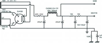
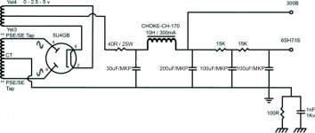
I'm not sure I fully understand your question. You threw me off for a bit with the "mkF" rather than "uF". Anyway... The capacitances in your schematics look pretty reasonable, except the capacitor on the output of the 5U4 in the first schematic. I don't think the 5U4 can survive that much cap, but check the data sheet. 30 uF sounds more reasonable for that - as you have in your second schematic.
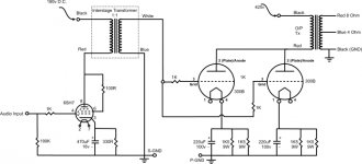
One note on your amp schematic, though. You can get rid of some caps in the signal path by converting the output stage to fixed bias. Instead of connecting the secondary of the inter-stage transformer (blue wire) to ground, connect it to an adjustable negative supply. You'll need somewhere around -65~-90 V on that node. Then just ground the cathode of the 300B. That eliminates two expensive caps and four 9 W power resistors. You'd probably want a slightly lower B+ if you do that...
~Tom
Thanks very much for your answer ,Tom!
I checked. For 5u4 capacitor must be 40uF.
I'll put this value in my scheme.
I really like your suggestion to move the fixed bias.
But I think I have a problem with the B + voltage to decrease ...
I already transformatorele (Tribute - The final word in audiotransformers)
2 pcs power supply C-core transformers
prim.240V / sec.425-0-425V/250mA / sec.5V/3A /
sec.7, 3V/2A (2x) / sec.3 0.15-0-3, 15 V / 2.5 A (2x)
2 pcs 10H/200 mA power supply chokes amorphous
2 pcs 10k/10k 10mA amorphous interstage transformers
2 pcs PSE 1k25/4-8R 200mA output transformes amorphous
Is there a solution to lower the B + up to 375 ... 385V?
Thank you very much!

Most 300B tubes run quite well at 400 V. That's where I run mine.
For lowering the B+, you have a few options:
1) Use a series resistor to drop the voltage. This would allow you better filtering as you could use an RC filter after your LC filter. You'll burn quite a bit of power in that series resistor, though.
2) Use a B+ regulator such as my 21st Century Maida Regulator (see my website). You'll still burn the same amount of power, it'll just be dissipated in a semiconductor rather than a resistor. But the supply impedance would be really, really low (< 0.05 ohm throughout the audio band).
When I found myself in a situation similar to yours, I ended up getting a new power transformer...
~Tom
If the power supply is giving 425V now, it is fairly easy to reduce it to 360V-380V:
Just change the first 250uF after the rectifier to 470nF 1000V FKP/MKP (LCR components type PC/HV/S is recommended for this position see Farnell).
PC/HV/S/WF 470NF 1KV - LCR COMPONENTS - CAPACITOR, 470NF, 1000V | Farnell United Kingdom
The value of the 470nF can be varied from 220nF to 1.5uF to adjust the voltage output, once you have the amp running.
This change makes the power supply into a (quasi) "choke-input" supply (you can look this up). If your choke is a Tribute 10H/200mA, it will work perfectly in this duty, provided the 300Bs are biassed to keep the total supply current below the rated value.
Choke-input supplies have many advantages: the "conduction-angle" of the rectifier is much greater, which reduces the rms current (and therefore the stress) in the transformer and rectifier. The regulation (change in output voltage vs. current) is also improved. More subtly, the reduction in rectifier peak current means that there are less electromagnetic emissions from the transformer and wiring (which may get picked up by your signal circuits).
With such high-quality transformers, your amp deserves the improvement in the sound that choke-input should give you.
Another way to reduce some voltage: Change the rectifier to type 5R4GY or (BRIMAR or RCA) or Chatham 5R4WGY. These type drop more voltage than 5U4, and also sound noticeably better than 5U4. In this case, the first capacitor must be 4uF or less - but again, choke-input will be better still.
Power supply output voltage depends on several factors:
example
- P. S. transformer secunder parameters (voltage, DCR);
- rectifier tube drop voltage;
- choke or capacitor input;
- first capacitor value;
- choke DCR;
- load
etc.
If you decrease first capacitor (3u3 in my schematic), then output voltage lessen, but hum will increase.
IMHO 200uF too much, in my practice in such case sound too "slow".
Attachments

Thank you very much everyone ,very useful information for me!
I have experience only with Class A amplifiers .
Photo and image hosting, free photo galleries, photo editing
But I heard from my friend a PSE300 from Audio Note and I liked very much.
I hope my amplifier speakers sound good with CORAL 10 .
Best regards🙂
I have experience only with Class A amplifiers .
Photo and image hosting, free photo galleries, photo editing
But I heard from my friend a PSE300 from Audio Note and I liked very much.
I hope my amplifier speakers sound good with CORAL 10 .
Best regards🙂
- Status
- Not open for further replies.
- Home
- Amplifiers
- Tubes / Valves
- pse300B