I thought it might be like that, I was just drawing it as you posted.
In that case, I've drawn what should be the pinouts for your ballast. I'm pretty sure they're correct, because from your last photo, the PCB traces would also match.
To fool the projector to stay on, you should be able to just short-circuit the "Lamp Lit" signal (left-hand pin) to GND (center pin.)
Remember, the diagram is looking at the underside of the board, so you'll have to translate that to whichever wire it is on the connector!
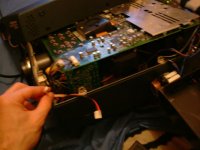
You do NOT need your ballast to be powered for this (ie. you should unplug the power to the ballast - the connector with the thick black and red wires)
Again, I'm confident this is the correct pinout, but I accept no responsibility for electrocution or damage to property! You should always stay well away from a projector when it's powered with the lid off!
In that case, I've drawn what should be the pinouts for your ballast. I'm pretty sure they're correct, because from your last photo, the PCB traces would also match.
To fool the projector to stay on, you should be able to just short-circuit the "Lamp Lit" signal (left-hand pin) to GND (center pin.)
Remember, the diagram is looking at the underside of the board, so you'll have to translate that to whichever wire it is on the connector!
You do NOT need your ballast to be powered for this (ie. you should unplug the power to the ballast - the connector with the thick black and red wires)
Again, I'm confident this is the correct pinout, but I accept no responsibility for electrocution or damage to property! You should always stay well away from a projector when it's powered with the lid off!
Attachments

"You should always stay well away from a projector when it's powered"............aa-men to that brother..
you solved the riddle just like that bam bam bam. i'm gonna go through all the notes and try to break anything......
a big big thank you to you first of all OzOnE_2k3. i need to pick your brain somemore in a couple hours! i hope your around..i finished uni so i'm buming around for a while..but got a couple things to do but i'm gonna keep you posted 100%..the ONLY difficult part is getttin the bits back in! also would it not be possible then just to short the cable and remove the whole psu? or do i need that trasnistor thingy to be there?
thanx a bUnCh.
in a bit....
dj holmes
You should be able to remove that ballast completely if you're sure the "lamp lit" bypass works before you chop any connectors off or anything.
OzOnE.
P.S. Sorry, I'm not taking the pee, but that typo is a classic! "i'm gonna go through all the notes and try to break anything " !! I love it, sounds like something I would do.
OzOnE.
P.S. Sorry, I'm not taking the pee, but that typo is a classic! "i'm gonna go through all the notes and try to break anything " !! I love it, sounds like something I would do.
o.k i tried to short the follwoing pins....
key pin 1 = lamp on
i have shorted
lamp to ground =effect= lamp warning light then shutdown
ballast to ground = effect= =lamp warning light then shutdown
ballast to lamp =effect= lamp " " " " "
i did not try to short all three. man i knew it! no one has my pj it must be one of those funny ones. but those funny ones laways happen to me!!!?!?!? am i cursed or what. i even have a couple of cyrstals for positive enerygy etc! but i think its faulty!!!! LOL
any idea on how much this projector is worth anyway??
also how in gods name did you manage to find out what pins switch the light on etc? looks like i'm gonna have a late night but i will on this first thing early evening (when i wake up!!! YA BABY)
OzOnE_2k3 how much experience do you have in electrcal fields? also where in uk are you based. thanx buddy
Attachments
Hi dj_holmes,
Sorry to hear about the PJ. Has it been tested before with the original lamp, or is the lamp probably broken? If the projector didn't work before (with a known good lamp), it could be due to a broken (or jammed) fan, a blocked dust filter, an interlock switch, the power supply, or worse - the main board!
If the projector worked before with an original good lamp, the ballast bypass might not be working due to that old timing problem.
The way I found the pinout of the connector was simply looking at the datasheet and finding which pins on the optos joined to which pins on the connector. The fact that you can see where three or four of the pins join on the underside of the board pretty much confirms that the optos were very unlikely to be the other way round. Some of the pins aren't even used on these optos (pin 3 = "n.c." = No Connection.)
Also, the pins which have those surface-mount resistors in line with the traces to the connector are generally the supplies to the opto's internal LEDs. Those pins also matched the datasheet.
The pins on the connector which go to the opto's LEDs (1 and 2), are signals FROM the projector TO the ballast. And the pins on the connector which go to the opto's phototransistor pins (4 and 5) are signals FROM the ballast TO the projector.....
From this, you can give a good guess to which pins are the "lamp on" signal, and which are the "lamp lit" signal. It gets much more dificult to guess when there are more than two optos!
Note: These pinouts are only on your projector - opto pinouts can differ of course.
The only thing I couldn't be 100% sure on was the GND (ground) connection. This would only be relative to the PJs main boards, as there is no direct electrical connection between the main boards and the ballast board (once again - the whole point of using optos!)
dl_holmes, do you have a multimeter at all? If so, could you possibly test which pins on the optos join to the center pin on the connector? Alternatively, you might be able to see where the pins connect to by looking at the PCB traces and following them along. Sometimes though, they will pass through the PCB through a "via" (silver blob).
Please be VERY careful when testing, as the charges stored in these boards can easily KILL!! Even after the projector has been unplugged, the charges can stay there for weeks, or months!
If it is not a timing problem, it's probably the fact that the PJ works from voltage levels instead of logic signals to work out when the lamp is warming up etc. You would need to measure the voltage between the GND signal and the "lamp lit" signal when powering an original (good) lamp (danger Will Robinson!). This signal would then have to be faked somehow.
These are the only type of methods that I can think of for fooling these projectors without having any diagrams or service manuals to hand, or without having the projector in front of me!
I'm in Torquay btw. I'm not an engineer or anything, but I've self-taught by repairing video recorders, power supplies, laptops and many other things over the years. (I'm still only a spring chicken though I hope, but electronics can often give you grey hairs!)
EDIT: Actually, if you could post some closeup photos (front and back) of the small board where the ballast signal cable connects, that might give us more clues as to how your PJ detects the "lamp lit" or "lamp OK" condition.
ITS ALIVE!!!!! i took the pj over to my mates house, after 2 hours of messing around my mate got the dam thing to stay on!!
i think 99.9% of it is down to you! OzOnE_2k3.............will do further test BUT IT WORKS NOW..... do you have paypal account OzOnE_2k3?
i think 99.9% of it is down to you! OzOnE_2k3.............will do further test BUT IT WORKS NOW..... do you have paypal account OzOnE_2k3?
Hi dj_holmes,
Excellent work my friend!
Yes, I have PayPal. I use eBay quite alot. I'll put me e-mail button back on here again if you need to contact me.
Care to share what your friend did to get it to work?
Excellent work my friend!
Yes, I have PayPal. I use eBay quite alot. I'll put me e-mail button back on here again if you need to contact me.
Care to share what your friend did to get it to work?
hi there ozone
i think my mate just put the cabling back inthe right order!!!!! that was it!!!??
i want to pay you for your work. i am computer engineer. i have many pc's for sale. i can give you one for free if you prefer. its not the greatest but it works. just need delivery cost.
the image below is a very early sample . just wanted to send proof that it works....the reason the image is red is beacuse i broke the ffc cable connectors. And i cannot find them anywhere. i was wondering AGAIN if you can help me? i JUST need the acual little connector that moves and locks the cable in position. the actual connectors are not damaged in anyway.
Attachments


i have seen a lot of commercial pj mods that have been made with car lights such as xenon and getting perfect results! i think i might head down the same path IF i can find that connector! either way i'm buying more projector!!!! what has been your experience lately? any advice ozone? thanks pal
Attachments
Hi,
How did you bypass the ballast? Did you just short the "lamp lit" pin to the Ground pin?
I'm also using a 50W 12V halogen lamp in my Proxima at the moment just for testing. It's actually not that bad. Obviously, it's not very bright, but you can watch things on it (apart from in the darkest scenes.)
I don't know what to say about the payment! I didn't think my ideas were worth much! If only I could find a job that pays me for the things I enjoy.
I wouldn't want to ask you anything for it. It's entirely up to you!
My tip for the FFC connectors (if you're desparate) would be to find a small piece of cardboard or plastic with the rght thickness shoved in above or below the cable to hold it's contacts against the connector pins. The cardboard or plastic should be the same width as the cable, and put in on the opposite side of the contacts. Hope that makes sense? This might not work for all FFC connectors though, and even if does it would probably start playing up after a short while.
I'm not sure where you'd get the same connectors from to steal the locks from, but FFC connectors are usually made by Molex, or Amphenol. You'd need to find out the pin spacing (pitch) and obviously the number of pins of the original connectors first. I had a quick look on RS and found a few possible candidates. Have a look at part number 458-3650, is it similar?.....
http://rswww.com
The minimum order amounts on credit card orders can be a pain in the bum with these companies for times like this!
The original connectors might even have the manufacturers part number printed on them, you could just Google to find the proper part then.
Is it just the one connector that's broken, or a few of them? Do you still have the locks, or are they missing? You could try the cardboard trick if you're desparate, but be careful not to break the ribbon cables!
I also fix PCs quite alot and I used to work in a computer shop (mostly unpaid!). After about 10 years, I'm sure it will start to stress you out 🙂 I'd love to do Home Cinema installation or something like that, but there's not much call for it around here unfortunately.
How did you bypass the ballast? Did you just short the "lamp lit" pin to the Ground pin?
I'm also using a 50W 12V halogen lamp in my Proxima at the moment just for testing. It's actually not that bad. Obviously, it's not very bright, but you can watch things on it (apart from in the darkest scenes.)
I don't know what to say about the payment!
I didn't think my ideas were worth much! If only I could find a job that pays me for the things I enjoy.I wouldn't want to ask you anything for it. It's entirely up to you!
My tip for the FFC connectors (if you're desparate) would be to find a small piece of cardboard or plastic with the rght thickness shoved in above or below the cable to hold it's contacts against the connector pins. The cardboard or plastic should be the same width as the cable, and put in on the opposite side of the contacts. Hope that makes sense? This might not work for all FFC connectors though, and even if does it would probably start playing up after a short while.
I'm not sure where you'd get the same connectors from to steal the locks from, but FFC connectors are usually made by Molex, or Amphenol. You'd need to find out the pin spacing (pitch) and obviously the number of pins of the original connectors first. I had a quick look on RS and found a few possible candidates. Have a look at part number 458-3650, is it similar?.....
http://rswww.com
The minimum order amounts on credit card orders can be a pain in the bum with these companies for times like this!
The original connectors might even have the manufacturers part number printed on them, you could just Google to find the proper part then.
Is it just the one connector that's broken, or a few of them? Do you still have the locks, or are they missing? You could try the cardboard trick if you're desparate, but be careful not to break the ribbon cables!
I also fix PCs quite alot and I used to work in a computer shop (mostly unpaid!). After about 10 years, I'm sure it will start to stress you out 🙂 I'd love to do Home Cinema installation or something like that, but there's not much call for it around here unfortunately.
man your genuine! hard to find in england.
i dont have paypal or ebay but my good mate has both. if you want have a look at his auctions if you like something i give to you on discount. i've also been fixing computer for years including oher peoples for FREE!! theres no money incomputers only programming!!
to get the pj to work.....
i followed YOUR instructions dis-connect and then Carefully re-connect and you have a modded commercial pj. FORGET building pj just mod commmercial ones why....
brighter images
sharper images
CHEAPER (believe it or not!)
smaller
less heat
less light leakage
3 x lcds!!! diy will NEVER MATCH THAT LOL! etc etc..
forgot to mention remote!! even though i didn't get one 🙁
i thought about the plastic bit under the ffc will fiddle latere and post more pics............thanx again ozone....i will send you the ebay name by e-mail if you want. tell me what you want and its yours! (has to be cheap, like me!LOL)
o.k this is progress....
the pj works without ballast and just the shorting of the pins!
i had a 75w halogeon(spelling?) one of the ones with a glass front and i tried it and boy it worked perfectly....
one leg was broken so it took me a hour of soldering, then braking, then soldering...etc
i was just about to take a picture when the atx powersupply blew!!!
the images WAS only visible in darkness but was quite clear. i even put a piece of paper under the fcc cable and it worked BEAUTIFULLY!!!!!!! the pj is not damaged or broken in any way!! (thats a first for me!)
man the image was better than i hoped!
i stuck the light right nex to the glass and made a housing for it...after nearly 5-10 mins the bulb and glass on the pj was very HOT!! how hot does you 50 run ozone??
ozone i know you done similar, any tick or tricks thanx. me thinks a 150w hqi would be way too hot? no? how hot are the orignial buols that run inthese pjs thanx
Hi,
I think some ATX supplies might need to be fairly well balanced with regard to which how much current is drawn from each voltage. eg. if you're drawing quite a large current from the 12V rail for your lamp (6.25Amps / 75W), and there's not much current being drawn from the 3.3V or 5V lines, then it's possible that this might stress some ATX supplies?
That's only a theory though! The more obvious been that the cheap ATX PSUs that come with the cheap cases these days are usually total CR*P! I had about four friends who'd all bought those "Nokia" style cases, and within about 6 months, every single one of the power supplies blew up! That's why I always buy a farily expensive PSU.
Anyway, rant over. 😉 Great to hear you were getting good pictures from the 75W bulb. I have to say, the 50W bulb really isn't that bad, but you need the room in perfect darkness to see the image. I'm still waiting for my white LEDs 🙁
I don't really know how hot the bulb gets on the Proxima. It has quite a big fan (92mm), so it seems to cool it down enough. I should be more worried about the colour wheel in mine though, as I had to unplug the small fan next to it 'cos it was one of the noisyest things. Hopefully, colour wheels will be a thing of the past in the near future!
I also have no idea what the average temps of the original halide type lamps are? Keep in mind that your lamp housing does have a temp limit switch on which should protect the projector from the highest lamp temps. Is the lamp still quite far away from your LCD panels? (ie. in the original lamp housing?)
Do you know what that FFC connector was for at all? (as Alan Partridge would say: "Just curious!")
Oh, forgot to add: I was chatting with throwit the other day about bypassing the fans on his PJ..... You would have thought that most two-pin fans could simply be unplugged, but his Infocus kept shutting down anyway. So, I finally caught on that they'd have chips by now which could detect the fan RPMs just by using standard two-pin fans! The chips just detect the current pulses on the power wires as the coil "commutates" inside the fan. Microchip make versions of this type of chip.....
http://ww1.microchip.com/downloads/en/DeviceDoc/21734a.pdf
So, the plot thickens where fans are concerned as many new projectors will probably make use of these chips. The chips can be programmed to tell the projector if a fan has dropped below a set RPM limt, and can also tell if a fan goes short-circuit or open-circuit / unplugged. It may be possible to bypass these sort of chips on some PJs by cutting a PCB track, then soldering a wire between two points. But, many PJs would probably read the data from the data bus, and this would need some sort of modchip in order to bypass the fans!
You could try replacing the fans, but when throwit tried this on his Infocus, it still shut down because the new fan probably span at a different RPM.
hi there,
you are absolute about the fans.. i think my pj did not work because of that EXACT small very noisy fan you are talking about. even though mine is 3 pin. also that atx was as old as shite so i'm not too concerened about it. i just dont want it to happen again!
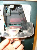
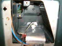
also here is the LCD and its RBG ffc's please not the fcc connection the pins are at the top and the clip goes on the BOTTOM. pushing the fcc up into the pins.
you are absolute about the fans.. i think my pj did not work because of that EXACT small very noisy fan you are talking about. even though mine is 3 pin. also that atx was as old as shite so i'm not too concerened about it. i just dont want it to happen again!
also here is the LCD and its RBG ffc's please not the fcc connection the pins are at the top and the clip goes on the BOTTOM. pushing the fcc up into the pins.
Attachments

what about xenon light that every one is using? its seems pretty straight forward...ballast bulb 12-16v input = many lumens! any opinions? thanx
Where has this thread gone??
Yo spuds ???? Is there any more info relating to this thread??? It seems Like it died in 2006. This may be a short Money Mod to a great DIY Projector. There are millions of these on already the used Market!! A great projector Like this with a short Money retro fitted Lamp would Be a Great investment that would last Lifetime. I am surprised that there hasn't been a LOT more Intrest in this. Djhomes and Ozone May really be on to something. If there is anybody who has actually done this mod and it has worked. Please reply in this forum/thread and Feel free to email me privately at Stuffyhead1@aol.com
Many thanks in advance.
Bohanna
- Status
- Not open for further replies.
- Home
- General Interest
- Everything Else
- The Moving Image
- DIY Projectors
- proxima 5900 MOD HELP PLZZ