i have projector in bits trying to retro please help.
throwit ..projector ballast is different from this one and i cannot even find the chips that he mentions...AC CE etc
also i have read how people have just shorted the bulb connection and have fooled the pj into switching on! i'm not sure if i understood that right? no way am i taking the risk of trying, ui have had too many bad memories of things blowing up!
please help. trying to disable ballast (not really important)
enable lcd (fool pj)
any advice or tips as i am always searching thanx
Attachments
Hi, dj_holmes,
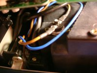
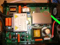
Please be careful with the electrics etc.! The thing on top of the lamp housing is the temperature limit switch. This is connected in series with the mains supply so that if the lamp / housing reaches a pre-determined temp limit, it will cut the mains supply to the PJ.
For some reason, they generally don't insulate these things very well, so I wouldn't recommend going anywhere near it (or the power supply / lamp etc.) if you're powering the PJ with the cover removed.
The temp limit switch has a button in the center which will pop-up if the temp limit is reached.
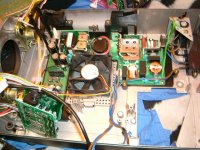
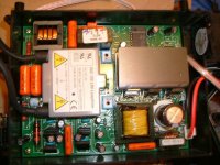
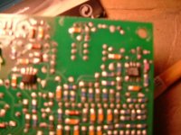
Do you possibly have a closeup photo of your lamp ballast (it might be that board in the bottom-left of the photo in post #3, or it might be part of the main power supply)?
If the ballast is separate, then you should have the cable(s) to the lamp on one side, and the power input and ballast on/off signal cable on the other side?
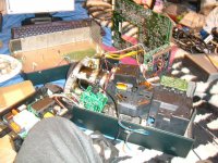
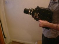
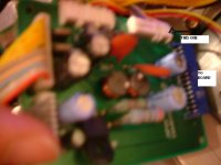
EDIT: Actually, I just noticed your ballast is that huge thing on the left-hand side of the photo in your first post (no, not your knee!). If you could post a closeup of the connections that go to the projector, we might be able to work out how to fool it. The signal wires are usually thinner than the other wires.
Please be careful with the electrics etc.! The thing on top of the lamp housing is the temperature limit switch. This is connected in series with the mains supply so that if the lamp / housing reaches a pre-determined temp limit, it will cut the mains supply to the PJ.
For some reason, they generally don't insulate these things very well, so I wouldn't recommend going anywhere near it (or the power supply / lamp etc.) if you're powering the PJ with the cover removed.
The temp limit switch has a button in the center which will pop-up if the temp limit is reached.
Do you possibly have a closeup photo of your lamp ballast (it might be that board in the bottom-left of the photo in post #3, or it might be part of the main power supply)?
If the ballast is separate, then you should have the cable(s) to the lamp on one side, and the power input and ballast on/off signal cable on the other side?
EDIT: Actually, I just noticed your ballast is that huge thing on the left-hand side of the photo in your first post (no, not your knee!). If you could post a closeup of the connections that go to the projector, we might be able to work out how to fool it. The signal wires are usually thinner than the other wires.
lol...don't fire that thing in here you'll cause explosive decompression !
man that's a real quagmire of bits you have there, the first pic on the left (above your knee ?) looks like the ballast where you may find opto sensors, can you post a close up shot of that ?
matt
*lol, OzOnE, great minds mate 😉
man that's a real quagmire of bits you have there, the first pic on the left (above your knee ?) looks like the ballast where you may find opto sensors, can you post a close up shot of that ?
matt
*lol, OzOnE, great minds mate 😉
thats for your interest. not many men would stand up to the challenge let me tell you that now for nothing...but boy those german they are years ahead with their pj mods!
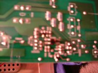
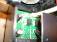
anywho i could not find a simgle trace of anything that looks like those funny sensors and this was the best i could find..it on the back of the main power board. its square and has 4 pins its the only one i could find!
anywho i could not find a simgle trace of anything that looks like those funny sensors and this was the best i could find..it on the back of the main power board. its square and has 4 pins its the only one i could find!
Attachments

Hi,
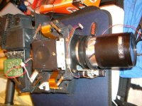
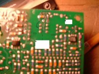
The EUC 120 L/00 is your lamp ballast (power supply). This would most definitely be a Philips ballast.
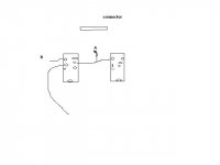
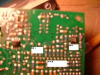
I've attached a copy of your photo.... It looks like the signal cable to the ballast is the one I've highlighted in green. If you could post a closeup photo of the area where it plugs into on the ballast, that would be great.
It probably plugs in behind that heatsink somewhere (highlighted in red.)
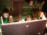
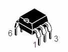
EDIT: Oh, just noticed your latest posts after I posted this one! The small six-pin devices in post #11 should be your optos. It should have a code on them? (you might need a bright light to see it though).
The EUC 120 L/00 is your lamp ballast (power supply). This would most definitely be a Philips ballast.
I've attached a copy of your photo.... It looks like the signal cable to the ballast is the one I've highlighted in green. If you could post a closeup photo of the area where it plugs into on the ballast, that would be great.
It probably plugs in behind that heatsink somewhere (highlighted in red.)
EDIT: Oh, just noticed your latest posts after I posted this one! The small six-pin devices in post #11 should be your optos. It should have a code on them? (you might need a bright light to see it though).
Attachments
See, Google's your second brain!.....
http://www.datasheetcatalog.com/datasheets_pdf/C/N/Y/7/CNY75A.shtml
You need to find out which pins on the optos connect to which pins on that cable connector somehow.
You can see in the datasheet that the optos have a small "notch" at one end so you can work out where pin 1 starts from.
Now, you can either take the whole thing apart so you can see the underside of the board to trace the tracks, or do you have a multimeter?
I can't seem to figure out where pin 1 of the optos start on your board when looking at the underside?
I've attached a picture of were pin one starts in comparison to where the small notch is on the top of your optos.... Could you possibly draw on the photo from post #17 again showing where pin 1 is on both optos? (remembering where it starts after you've flipped the board over of course).
I've attached a picture of were pin one starts in comparison to where the small notch is on the top of your optos.... Could you possibly draw on the photo from post #17 again showing where pin 1 is on both optos? (remembering where it starts after you've flipped the board over of course).
Attachments
- Status
- Not open for further replies.
- Home
- General Interest
- Everything Else
- The Moving Image
- DIY Projectors
- proxima 5900 MOD HELP PLZZ