Dear sirs
I put a topic here, something I had in mind for some time already, but for professional reasons, was always limited by the lack of time.
The question is a personal project, which personal and professional knowledge I decided to build an active preamp (solid state) that has lasted eight years your development
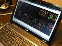
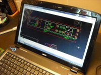
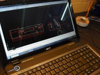
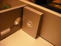
With the help of software Auto-CAD in conjunction with our imagination is possible to create a housing with a personal designer.
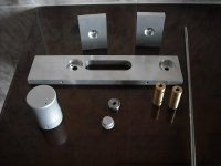
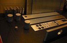
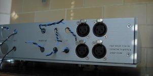
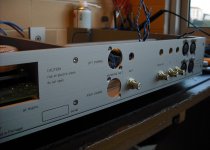
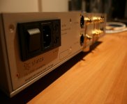
The housing material is aluminum. Has two RCA inputs and two input xlr. Has one RCA output and one xlr. The front panel has an input selector and one attenuator. On the right side is the standby button.
The pot attenuator is an ALPS modified. Inside, Teflon is used to dampen the vibrations of the box..
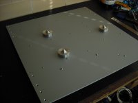
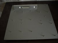
The supporting foot are stainless steel. 3 foot is used at strategic points to reduce the resonance.
I enclose photos. then inform details of the preamp circuit and power supply
note: my English is somewhat bad, there may be some errors. I'm sorry.
jon
I put a topic here, something I had in mind for some time already, but for professional reasons, was always limited by the lack of time.
The question is a personal project, which personal and professional knowledge I decided to build an active preamp (solid state) that has lasted eight years your development
With the help of software Auto-CAD in conjunction with our imagination is possible to create a housing with a personal designer.
The housing material is aluminum. Has two RCA inputs and two input xlr. Has one RCA output and one xlr. The front panel has an input selector and one attenuator. On the right side is the standby button.
The pot attenuator is an ALPS modified. Inside, Teflon is used to dampen the vibrations of the box..
The supporting foot are stainless steel. 3 foot is used at strategic points to reduce the resonance.
I enclose photos. then inform details of the preamp circuit and power supply
note: my English is somewhat bad, there may be some errors. I'm sorry.
jon
Attachments
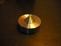
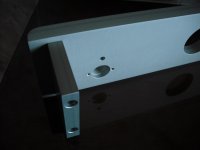
the pieces were made on my specifications in company specializing in aerospace.
Attachments


that's a serious DIY in there Jon, a very detailed construction and well planned project huh. Well done and good luck with your build mate.
that's a serious DIY in there Jon, a very detailed construction and well planned project huh. Well done and good luck with your build mate.
thanks junie
Mention of aerospace and it must be more than rather expensive!
Or someone repaying a big favour. Friends help sometimes.
Between 30 and 46years ago I got three little jobs done in Ferranti.
I await further details, both pics and description/specification
Or someone repaying a big favour. Friends help sometimes.
Between 30 and 46years ago I got three little jobs done in Ferranti.
I await further details, both pics and description/specification
Last edited:
Looks fantastic. But it´s rather expensive, I believe, no ?
yes it is a "little" expensive
best regards
jon
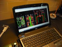
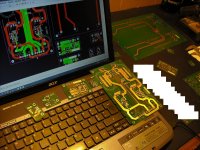
pcb layout
The software used for the design of the board is the Altium Designer... excellent, sophisticated and with a margin of error "null". The best that has passed through my hands.
Link:
http://products.live.altium.com/#r10/explore/bd-PcbLevelDesign
regards
jon
The software used for the design of the board is the Altium Designer... excellent, sophisticated and with a margin of error "null". The best that has passed through my hands.
Link:
http://products.live.altium.com/#r10/explore/bd-PcbLevelDesign
regards
jon
Attachments
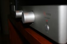
very nice Jon, I admit this is the first time I see a roller bearing used in the amp 🙂..and I have made many custom amp chassis...
best, TeguhPS
best, TeguhPS
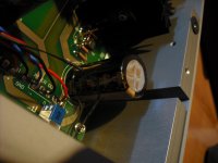
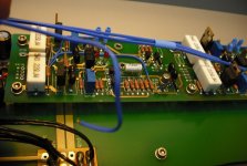
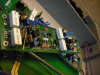
Power supply
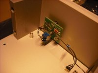
Consists of two bus (positive) and (negative). Each bus has four diodes ultrafast, 15 A, 35 ns (MUR1520) of ON Semiconductor, the capacitor are the from Nichicon KG (Gold Tune), totaling in all 47200 uf . (four 6800UF and two 10000uF).
The regulation this based on JFET (PN4393) Fairchild, (do not use 2sk170 because of counterfeits) and also I had better response with this model.
In series with the JFET this a zener (1N5250). From this point of reference there is an amp that goes to the output transistors of the power supply. (ECX08N16-Z) positive rail and (ECX08P16-Z) negative rail.
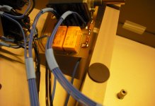
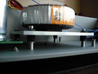
To prevent vibration the transformer is suspended on shock absorbers to neoprene
There is also a small circuit in the power supply that is responsible for the mute / standby. In reality the whole circuit is designed to be connected to the current 24 hours per day.
regards
jon
Consists of two bus (positive) and (negative). Each bus has four diodes ultrafast, 15 A, 35 ns (MUR1520) of ON Semiconductor, the capacitor are the from Nichicon KG (Gold Tune), totaling in all 47200 uf . (four 6800UF and two 10000uF).
The regulation this based on JFET (PN4393) Fairchild, (do not use 2sk170 because of counterfeits) and also I had better response with this model.
In series with the JFET this a zener (1N5250). From this point of reference there is an amp that goes to the output transistors of the power supply. (ECX08N16-Z) positive rail and (ECX08P16-Z) negative rail.
To prevent vibration the transformer is suspended on shock absorbers to neoprene
There is also a small circuit in the power supply that is responsible for the mute / standby. In reality the whole circuit is designed to be connected to the current 24 hours per day.
regards
jon
Attachments

very nice Jon, I admit this is the first time I see a roller bearing used in the amp 🙂..and I have made many custom amp chassis...
best, TeguhPS
thank you TeguhPS</SPAN>
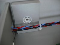
Bearings are used in combination to the buttons to have a smooth slide. I changed the bearings of steel to nylon, because they caused .... analytical sound!!!
later with pictures on this topic
best regards
jon
</SPAN>
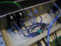
line stage (description)
Each channel consists of two blocks of amplification, but only one is responsible for signal amplification with a gain approx 11dB.
The other block has a gain 1:1, and load your own power supply. It acts as a shunt regulator, the big difference, the audio signal to move in himself.
the description of line amplifier:
Differential input with a double Jfet custom (2N5566 Vishay Siliconix). The type used is industrial version. The 2N5566 is powered by a current source. The output of this follows a cascode composed by transistor bipolar (Zetex) and mosfet.
Output: a voltage follower is composed by lateral mosfet (Hitachi).
Not used capacitors in the signal path.
There transistors coupled mechanically to avoid offset in the output.
Not used circuit servo, to maintain the purity of the signal.
It´s used Vishay resistors RN55D, RN55C; Caddock MK132; IRC and Welwyn
it's used capacitor Vishay Roederstein MKP 1839 HQ and (MKP 1845 (used on ac filter))
cable kimber and NeoTech
internal operating voltage + / - 20V
and… more photos
(cumprimentos a todos os diyers)🙂
jon
Attachments


after several tests replace the cable Kimber, for to NeoTech legenburg (only the audio signal) obtained a very good result.
best regards
jon
best regards
jon
Attachments
thank you TeguhPS</SPAN>
Bearings are used in combination to the buttons to have a smooth slide. I changed the bearings of steel to nylon, because they caused .... analytical sound!!!
later with pictures on this topic
best regards
jon
</SPAN>
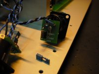
hello ide2003
good morning
here's the pictures of nylon bearings...
Attachments
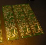
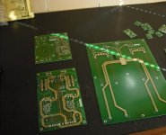
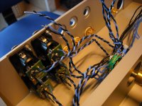
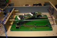
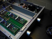
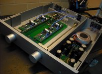
more photos of the construction
jon
jon
Attachments
Last edited:
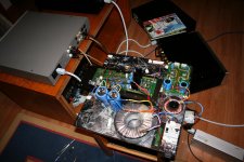
Do not be scared.🙂
It's my power amplifier in development.
the concept is the same as found on this link: (very good)
http://www.diyaudio.com/forums/solid-state/186650-jfet-input-mosfet-vas-lateral-output-perfect.html
good job to all
Greetings to all DIYers
jon
It's my power amplifier in development.
the concept is the same as found on this link: (very good)
http://www.diyaudio.com/forums/solid-state/186650-jfet-input-mosfet-vas-lateral-output-perfect.html
good job to all
Greetings to all DIYers
jon
Attachments
- Status
- Not open for further replies.
- Home
- Source & Line
- Analog Line Level
- prototype preamplifier