Comparator circuit is the same as I posted earlier. /OFF pulls the timing capacitor to ground, using a couple of diodes and a resistor to ruggedize the input. I'll post it later when I'm home.Read again, 6/12db is related to the 20db minimum gain, so 20db is considered as 0dB.
gmarsh, does your comparator-setup takes care of power-off-plop? Would you provide the setup as well as your gain setup?
Regards.
Turn-off pop isn't handled, but the turn-off pop is far quieter than the turn-on bang that you get when you don't provide a turn-on unmute delay.
I'll sneak those parts in. The datasheet example uses 10K and 1nF to filter the sync signal going from chip to chip, which makes a ~16KHz lowpass filter. With the switching frequency set to 1.2MHz, that can't work too well...Regarding synch pin - would it make sense to provide for a bypass cap and a series resistor / jumper around the synch pin as shown in the Typical Application circuit in the data sheet (figure 37, page 26). It looks like there is room, and more could be gained if the two vias were rotated 90 degrees clockwise.
You should be able to get by without synchronizing for most applications. The decoupling design should keep switching frequency content off the power supply. And unless you jam two boards side-by-side so that L1/L2 are practically touching, you shouldn't get any significant magnetic coupling.
Turn-off pop isn't handled, but the turn-off pop is far quieter than the turn-on bang that you get when you don't provide a turn-on unmute delay.
Well, then you may drop the second comparator.
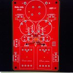
My attempt @ a 'proper' TDA3118 PCB.
4 Layer Board with GND on the 2nd layer - 120mm x 80mm
3118 or 3116
LL1540 LUNDAHL
Mundorf 4-pole Cap
Bourns 2200H
Rubycon ST 2220 + 10mm Oscon x 2 + 0603 per side
YMMV.
Dwight
4 Layer Board with GND on the 2nd layer - 120mm x 80mm
3118 or 3116
LL1540 LUNDAHL
Mundorf 4-pole Cap
Bourns 2200H
Rubycon ST 2220 + 10mm Oscon x 2 + 0603 per side
YMMV.
Dwight
Attachments
I'll sneak those parts in. The datasheet example uses 10K and 1nF to filter the sync signal going from chip to chip, which makes a ~16KHz lowpass filter. With the switching frequency set to 1.2MHz, that can't work too well...
Thanks.
The datasheet example uses 10K and 1nF to filter the sync signal going from chip to chip, which makes a ~16KHz lowpass filter. With the switching frequency set to 1.2MHz, that can't work too well...
The synch frequency is in the order of 100kHz. The incorrect values have been noted for the next data sheet revision. The suggested values give a cutoff of 720kHz.
TPA3116D2 in 2.1 master/slave mode - Audio Amplifiers Forum - Audio Amplifiers - TI E2E Community
"Yes the RC values need to be reduced. 4.7K Ohms and 47pF would work well. This is already noted for the next DS revision. Thanks."
and
TPA3116D2 ? About slave mode - Audio Amplifiers Forum - Audio Amplifiers - TI E2E Community
"The SYNC freq should be in the range of 100KHz +-10% for optimal operation. The internal PLL will provide the desired PWM siwtching freq based on the AM pins settings."
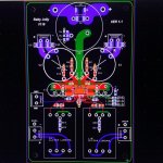
Added sync components. TPA sync pin -> series R -> shunt C -> via. Current top shot:


Yeah, pulling /OFF low pulls SDZ low on the TPA, dropping the standby current to a couple mA. I could do a lower standby current but I'd want to put the microcontroller back in for that.power off here is standby isn't it?
can you show bottom layer .
TY
Last edited:
Read again, 6/12db is related to the 20db minimum gain, so 20db is considered as 0dB.
.
I was thinking 26 should be nominal
weird logic I reckon > Minimum = Nominal.
Gmarsh thanks
I see you didn't use any fancy ground plane current routing slices.
I thought the ref design shows a "hogged out" area
I see you didn't use any fancy ground plane current routing slices.
I thought the ref design shows a "hogged out" area
Last edited:
Both DIP switches off: 20dB
+6dB DIP switch on: 26dB
+12dB DIP switch on: 32dB
Both DIP switches on: 36dB.
The DIP switches just determine the voltage on the GAIN/SLV pin.
I don't think this design needs ground plane slices. I've used those in mixed signal analog/digital/RF designs and SMPS designs, where I've needed to keep things as electrically 'separate' as possible.. that situation doesn't really exist here. All the high power stuff is west of the TPA, no significant current will flow in the ground plane to the right of the TPA, so the analog stuff over there is pretty safe.
ground slicing > small loop areas are good and even better when fenced off
Im sure it'l be fine
Im sure it'l be fine
Last edited:
Def want a few of these boards! Looks great. Prefer to pay you rather than the YJ rip off version...
YJ is very Chinese, like Landwing e32 copied RangeRover Evoque and like Jiangling T7 copied Volkswagen Amorak. It isn't ripoff, its Chinese. YJ copies everything they like to sell or everything they try to push original seller out of market. Capitalistic China has no rules.
"rip off" as in they like to stalk this forum and others and then copy-- verbatim, designs they find here.
The YJ blue-black board was designed by a forum user named "Danzz."
so again, I would prefer to pay the actual designer for the work, pay a few bucks more, than pay the people who steal intellectual property and work.
If possible, I will buy 3-4 boards direct this time rather than buy the YJ "rip-off" version--if one should appear.
I hope this explains what I meant by "rip-off" in this context.
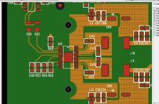
An layout that works for us.
Only output LC filter capacitor should be better than ours. It is for a library closing warning system. So no high quality is need here and therefore the output filtercap is cheap.....
But the rest is as it should be.
PS: board is a 4 layer..
Only output LC filter capacitor should be better than ours. It is for a library closing warning system. So no high quality is need here and therefore the output filtercap is cheap.....
But the rest is as it should be.
PS: board is a 4 layer..
Attachments
Last edited:
Thanks for that."rip off" as in they like to stalk this forum and others and then copy-- verbatim, designs they find here.
The YJ blue-black board was designed by a forum user named "Danzz."
so again, I would prefer to pay the actual designer for the work, pay a few bucks more, than pay the people who steal intellectual property and work.
If possible, I will buy 3-4 boards direct this time rather than buy the YJ "rip-off" version--if one should appear.
I hope this explains what I meant by "rip-off" in this context.
I fully expect this board layout to be copied, and finished boards to be sold on eBay for half the price of the parts alone on Digikey/Mouser, because they'll be using god knows what for part selection. Hopefully not keeping the "GMARSH" text on the PCB if they do that...
Maybe you could take a page from DEC and add "GMARSH - when you care enough to steal the very best" to the PCB someplace.
Molecular Expressions: The Silicon Zoo - Steal The Best
Molecular Expressions: The Silicon Zoo - Steal The Best
Looks good!An layout that works for us.
Only output LC filter capacitor should be better than ours. It is for a library closing warning system. So no high quality is need here and therefore the output filtercap is cheap.....
But the rest is as it should be.
PS: board is a 4 layer..
- Status
- Not open for further replies.
- Home
- Amplifiers
- Class D
- "Proper" TDA3116 PCB