Right now, 50x96mm. Four holes in the corners 4mm from the board edge that are sized for a 4-40 or M3 screw.My idea with the Hammond enclosure was that the pcb slides and sits/rides along the Al extrusions designed for such. The pcb only needs attachment at the end plates. One can make a simple aluminum bracket to some how use the Hammond case as the heat sink for the TPA3116, saving $ on a fancy HS or extending the one that is chosen.
The Hammond 1455J1201 requires a pcb that is 75(w)x120(l)mm, what are your current dimensions?
Good luck with your design.
Tallest component so far is 16.3mm for the class D output inductor. Board is 1.6mm thick, I suggest 4mm standoffs, so total height is 22mm. Floor to ceiling clearance in the 1455J1201 is 24mm, so it'll fit.
Though there'll be 12mm between the card edges and the case edges, which doesn't give you much depth for connectors on the end caps. J1601 (same case but 40mm longer) should definitely fit everything.
I'm keeping this a stereo board. I haven't looked at it but apparently there's a PBTL group buy in the works, I'll stay off their turf 🙂If you changed the design to pbtl/mono, I would assume you could have an even smaller board, and still more compact layout? Also, given the same speaker load, I would assume pbtl puts half the current through the IC, making cooling easier?
I'm just guessing here, these ideas could be completely silly.
Using two ICs in PBTL mode versus a single IC will give you double the idle loss, half the conduction loss, and two ICs instead of 1 to remove heat from.
Comparator circuit. LM393 may not be the final IC, component values aren't final.

You might want to look into my 2-comparator-design here:
http://www.diyaudio.com/forums/class-d/237086-tpa3116d2-amp-633.html#post4188711
Dunno if the 3116 behaves the same as the 3132D2, but guess so, this design takes care of popless on/off even on power loss. As far as i tested here, the SDZ is totally ignored on power-on, so having a time-constant on that pin changes nothing regarding the "plop". You might then rescale the thresholds to work for a wide range of PVCC. (Which mainly leads into my design then)
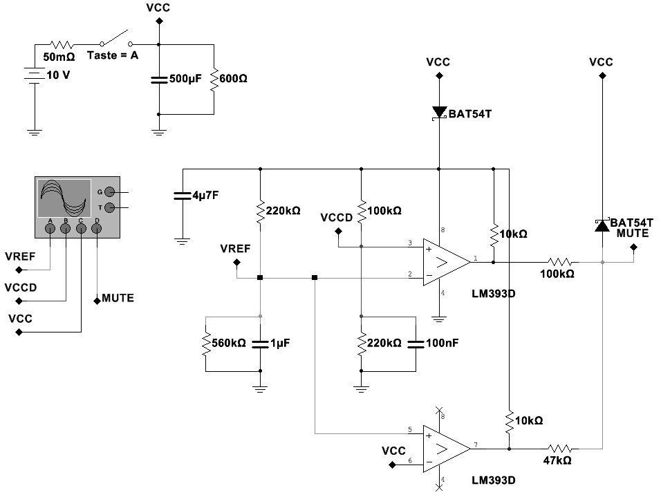
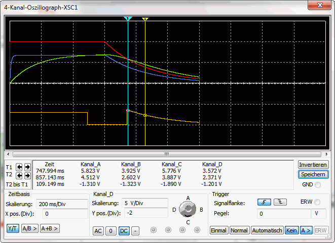
The point is to have enough juice to keep the rails of the comparators up to surely mute on power-down. I've tested this from a minimum of 10V with light load - works. Higher PVCC + higher load gives more safe margin.
Regards
Edit:
Having a cap to GND from the neg. input of the upper comparator would help to fix the power-off plop (if any) in conjunction with a blocking diode between PVCC and VCC of the comparator + some bulk capacitance beside em. (To hold the rails up)
Last edited:
Just noticed something in the TPA datasheet - in absolute maximum ratings, maximum slew rate is 10V/ms on the AMx, SDZ, MUTE and MODSEL pins. "If exceeded, use a 100K series resistor."
10V/ms is pretty damn slow.
10V/ms is pretty damn slow.
Oh, I figured out how to do gain selection with 2 DIP switches giving the 4 settings. Use a 30.1K resistor to ground, and 75K and 150K resistors to GVDD through DIP switches.
Saves dragging out a soldering iron to change the gain.
Saves dragging out a soldering iron to change the gain.
Being able to switch AM frequency and having better pop-performance will be fun. Is there a way to have proper working ampboard when people connect

I'm paraphrasing youAny special assembly tools
.... No, just normal stuff
Great!
I thought a hot plate might be needed for the SMD caps to ground plane / heat sink
gmarsh - this looks like it is coming along nicely. Have you exposed the synch and master / slave pins so these could easily be stacked and use for 4 channel output?
gmarsh,
Thanks for your efforts to design an "ideal" TPA3116/3118 Class D amp board. It's great when you and others with far more understanding and skills than me develop something that can benefit others. I still have my DUG group buy TPA3116 amps to assemble and I have high expectations for this amp, but I will keep an eye on this thread for this group buy as well (when it happens).
I'd like to request that you also include SMD solder pads for the surface-mounted inductors like the CoilCraft MSS 1583-223MEB/103MEB inductors.
http://www.coilcraft.com/pdfs/mss1583.pdf
14.8mm x 14.8mm footprint. I sent a set to friend who replaced the Bourns 2101-H-RC inductors on his modified Yuan Jing TPA3116 blue amp, and he said there is no comparison. The amp sounds much better with the CoilCraft inductors.
30.1% is in my 1% resistor kit and does the job just fine. I'm not making a million of these things at penny margins, so the cost difference isn't gonna break the bank 🙂30.1k, are you serious? 30k is avail. at E24.
I made a dumb excel spreadsheet to calculate the GAIN/SLV to GVDD ratios at worst case 5% resistor values (TI says use 5% or better), and made the DIP switch method fall within the range using 1% resistors.
Not yet, but I'll poke in side by side sync/ground vias to allow hooking it up. You'll have to mess with the GAIN/SLV resistors to put it in sync mode though, so this will be an 'expert' mod.gmarsh - this looks like it is coming along nicely. Have you exposed the synch and master / slave pins so these could easily be stacked and use for 4 channel output?
I don't doubt it sounds better, the MSS1583 has a stupidly flat inductance/current curve up to 8-9A. There isn't a published curve for the 2100 series but it's probably because it's not intended for applications where you want a flat curve.gmarsh,
Thanks for your efforts to design an "ideal" TPA3116/3118 Class D amp board. It's great when you and others with far more understanding and skills than me develop something that can benefit others. I still have my DUG group buy TPA3116 amps to assemble and I have high expectations for this amp, but I will keep an eye on this thread for this group buy as well (when it happens).
I'd like to request that you also include SMD solder pads for the surface-mounted inductors like the CoilCraft MSS 1583-223MEB/103MEB inductors.
http://www.coilcraft.com/pdfs/mss1583.pdf
14.8mm x 14.8mm footprint. I sent a set to friend who replaced the Bourns 2101-H-RC inductors on his modified Yuan Jing TPA3116 blue amp, and he said there is no comparison. The amp sounds much better with the CoilCraft inductors.
The MSS1583 won't fit on the my card horizontally (card's only 50mm wide) but you could glue them on their side to the PCB and jumper their pads to the PCB with <1cm of wire per leg. Should work pretty well electrically.
Latest:

Compared to last snapshot:
- Size is now 50x100mm instead of 50x96mm.
- Got rid of the microcontroller, now using a LM393 dual comparator for power-on sequencing. The /EN pin on the terminal block is now an /OFF pin, connecting /OFF to ground turns the amp off.
- DIP switches added for easy gain setting in master mode, labeled "+6dB" and "+12dB" even though with both switches on, the gain's actually +16dB 🙂 To use slave mode you'll have to open the DIP switches, change R16 and install a resistor at R17 to set the slave mode gain.
- Sync/ground vias added to the card, so you can strap multiple cards together and synchronize them.
- Added locations for output snubber using 0805 resistors/capacitors.
Latest:
DIP switches added for easy gain setting in master mode, labeled "+6dB" and "+12dB" even though with both switches on, the gain's actually +16dBTo use slave mode you'll have to open the DIP switches, change R16 and install a resistor at R17 to set the slave mode gain
how did you arrive at those 2 gain settings? or is that just for slaving
most amps run at 26 dB, and this data sheet shows that value throughout too.
can you show bottom layer .
TY
Thanks for adding the vias. This is the sort of 'expert' mod I can handle! Actually, I will probably just change the resistors so I an use the dip switch for gain adjustment but in 'slave' mode.
are you sure gains of 6 and 12 db are possible? The data sheet says there are 8 input states. The word states suggests that intermediate gain options do not exist
are you sure gains of 6 and 12 db are possible? The data sheet says there are 8 input states. The word states suggests that intermediate gain options do not exist
Read again, 6/12db is related to the 20db minimum gain, so 20db is considered as 0dB.
gmarsh, does your comparator-setup takes care of power-off-plop? Would you provide the setup as well as your gain setup?
Regards.
gmarsh, does your comparator-setup takes care of power-off-plop? Would you provide the setup as well as your gain setup?
Regards.
Last edited:
Regarding synch pin - would it make sense to provide for a bypass cap and a series resistor / jumper around the synch pin as shown in the Typical Application circuit in the data sheet (figure 37, page 26). It looks like there is room, and more could be gained if the two vias were rotated 90 degrees clockwise.
- Status
- Not open for further replies.
- Home
- Amplifiers
- Class D
- "Proper" TDA3116 PCB