The length of i2s and the ground wires is about 5 cm. Of course I understand that I2S wires should be as far from power supplies as possible. At least 20 cm.
The USB board is approximately 5 cm from the DAC board and it is above the DAC board somewhere in the middle of the DAC board because USB board is connected right to the DAC IC pins on the DAC board (PCM-56).
The USB board is approximately 5 cm from the DAC board and it is above the DAC board somewhere in the middle of the DAC board because USB board is connected right to the DAC IC pins on the DAC board (PCM-56).
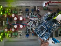
Also please note that the DAC board has 2 sections:
the digital section before the iolator and the DAC IC
the analalog section after the DAC IC including the DAC ic.
I disconnected power to the digital section. Therefore as you can see from the photo the USB board is attached atop the digital section of the DAC board which is not powered. So no RF or EMI coming from that section of the DAC board.
This is not good practice, so what you are hearing is consistent with the photo.
Perhaps Mark4w can help you, but there are real problems.
Perhaps Mark4w can help you, but there are real problems.
Last edited:
Unfortunately I can't place the USB board closer to the DAC board than it is now.
Also as far as I understand 5 cm is not too long for i2s wires.
And one more thing. I have another DAC with another converter (spdif to i2s converter) and there I hear the same results when I manipulate ground wires in the same way.
Also on the second DAC I use i2s balanced connection via RS-485. Not TTL but the results are similar to this.
So in my opinion the takeaway is that a similar change in sound quality would be present at any other DAC + converter combination out there if they are connected by wires.
This is the main message that I am trying to bring forward
Yes, it is clear that this type of layout can cause ground loops and pickup noise. The DAC board should preferably have a similar 2-row pin header as the USBI2S bridge connected to a ground plane. Then the boards can be connected with a flat ribbon cable and no ground loops should appear.
Well the second DAC that I use has exactly this type of preferable connection that you are talking about but I hear the same effect on that DAC as well.
Besides, this USB board must be conected right to the DAC ic pins. Otherwise the length of the i2s connection would be too big.
Besides, this USB board must be conected right to the DAC ic pins. Otherwise the length of the i2s connection would be too big.
Can you show us a picture of your second DAC board. Your picture of the first DAC made things much clearer than any of your explanations.
By the way on my second DAC I have been originally using computer flat ribbon instead of wires but then I found out that quality improves when I place differential pairs apart from each other, so I cut the ribbon into dif pairs and then later I came to conclusion that the best sound is achieved by putting a ground wire along each differential pair and this ground wire must be connected to the ground from one side only.
Here is a photo of the USB board atop the DAC board.
Its not quite clear to me if the dac board has a ground plane on the bottom side?
Also, where are the ground wires connected at the dac chip, to its ground pins? If so, does that connect to a ground plane or individual ground traces somewhere?
In addition, it looks like there are I2S wires running from the USB board to two different dac chips. It would probably be better to run only one set of wires from the USB board to one dac chip, then using existing traces on the dac board or local jumper wires to connect I2S signals from the first dac chip to the second dac chip.
It might also help to add some resistance in series with the I2S signals near where they connect the dac board. I2SoverUSB has 33-ohm series loading resistors, but you might be able add another 50-ohms or possibly a bit more in the middle of the resulting I2S signal transmission lines to help damp out all the reflections caused by so many discontinuities.
I could be wrong, but did you check and confirm that PCM56 takes standard I2S timing? I have impression that the standard I2S has the data train one clock tick lags what PCM56 requires.
On a different and most likely unrelated matter, they (the CD player makers) usually put an over-sampling filter, 8x for example, ahead of PCM56 on CD players of the like construction, and the post D/A reconstruction LPF are designed accordingly. I suspect the I2S signal that you're feeding into the PCM56 is not over-sampled. If that is the case, you probably would need to mod the LPF as well to get rid of the aliasing.
On a different and most likely unrelated matter, they (the CD player makers) usually put an over-sampling filter, 8x for example, ahead of PCM56 on CD players of the like construction, and the post D/A reconstruction LPF are designed accordingly. I suspect the I2S signal that you're feeding into the PCM56 is not over-sampled. If that is the case, you probably would need to mod the LPF as well to get rid of the aliasing.
I could be wrong, but did you check and confirm that PCM56 takes standard I2S timing? I have impression that the standard I2S has the data train one clock tick lags what PCM56 requires.
The attached diagram shows what I meant.

I2S timing: After the LRCK transition, at the first SCK transition, the LSB trailing last word is expected, and at the second SCK transition the MSB leading the next word is expected.
PCM56: After the LRCK transition, at the first SCK transition, the MSB of the next word is expected.
Of course not. I meant my second DAC with a different converterThere are no differential pairs on I2SoverUSB board.
My DAC was not designed by me. So I don't know. But I guess it has.Its not quite clear to me if the dac board has a ground plane on the bottom side?
The ground pin are connected to the ground pin on the DAC chip because this is the shortest route. Of course these pins are connected to the ground plane on the DAC boardAlso, where are the ground wires connected at the dac chip, to its ground pins? If so, does that connect to a ground plane or individual ground traces somewhere?
Of course not. I meant my second DAC with a different converter
Why not give some more details. Which converter, which dac, pictures ...
If your other converter has truly differential I2S output are you sure that your dac has differential I2S input? In most dacs I2S is single ended (TTL or CMOS).
Yes, you are right. The DAC has two DAC chips, left channel chip and right channel chip.In addition, it looks like there are I2S wires running from the USB board to two different dac chips. It would probably be better to run only one set of wires from the USB board to one dac chip, then using existing traces on the dac board or local jumper wires to connect I2S signals from the first dac chip to the second dac chip.
If I follow your advice and run only one set of wires from the USB board to one DAC chip and then use existing traces on the dac board or local jumper wires to connect I2S signals from the first dac chip to the second dac chip then the length of the trace from the USB board to the second DAC chip would become too long. I2S traces can't be that long, they must be as short as possible. And I want to tell you that on my DAC board the traces do not come from one chip up to another chip since these are two channels. Why on earth would we run signal traces from one channel to another one?
I thought about it some time ago but the manual to the USB board does not tell anything about resistors on the i2s line. So I guess may be such resistors were implemented on the USB board. Unfortunately there is no publicly disclosed schematics of the USB board.It might also help to add some resistance in series with the I2S signals near where they connect the dac board. I2SoverUSB has 33-ohm series loading resistors, but you might be able add another 50-ohms or possibly a bit more in the middle of the resulting I2S signal transmission lines to help damp out all the reflections caused by so many discontinuities.
- Home
- Source & Line
- Digital Line Level
- proper grounding and shielding in i2s connection