I'm hoping Harry/Jocko or others might weigh in on the design of a proper divider for digital audio applications. Specifically I'd like a 128Fs MCK at 24.576MHz, a 64Fs BCK, and the Fs LRCK.
My inital thought was a quality 24.576 clock oscillator feeding a CMOS monolithic synchronous counter. The problem is that the propagation delay is nearly 50ns, so I would worry that clock syncronicity is lost.
Second thought is a 49.152MHz clock, and all signals are generated by the counter. Now I have to worry about using a non-fundemental mode oscillator.
Add to this the idea that CMOS logic induces a lot of phase noise. (?) What is the alternative? ECL logic? Analog claims 4ps jitter added by an ECL gate.
I have to wonder at the quality of the dividers in chips like AD1896 compared to a solution that board members here would create.
Any thoughts? What would you use in such a circuit? (Jocko, if you chime in with part suggestions, I'll promise to buy--not sample--them. ^_^)
I'd go with the second solution. Feed the counters with the 49.152 MHz clock and latch all the counters' outputs with a 74574 driven by the 49M clock. You may want to use the same latch to reclock the data output by the 1896. So all your signals are latched at the same time 😉
I'm not aware of a monolithic CMOS 8 bit synchronous counter, but a PLD (PAL/GAL) will do a nice job (at the expense of a much higher supply current).
3rd or 5th overtone XOs are not that tricky. I have no references handy here, but a google search with "butler" AND "overtone" will give you some starting points. And I'm sure our XO specialists will come to your rescue 😛 IMHO, the hardest job will be to find the proper xtal. 🙄
Hope this helps
3rd or 5th overtone XOs are not that tricky
Yes folks we have a winner. The most preposterous statement yet posted on this forum!
Yes folks we have a winner. The most preposterous statement yet posted on this forum!
I would go with the Butler if you are going overtone.
Never used any of the ASRC stuff. Too digital for Mr. Analog RF.
Jocko
Never used any of the ASRC stuff. Too digital for Mr. Analog RF.
Jocko
ASRC
Acronym alert!
Association of Specialists in Cleaning and Restoration?
Academy of Sciences of the Czech Republic?
American Society of Classical Realism?
Advanced Scientific Computing Research?
Adirondack Stampede Charity Rodeo?
All your acronyms are belong to us.
Acronym alert!
Association of Specialists in Cleaning and Restoration?
Academy of Sciences of the Czech Republic?
American Society of Classical Realism?
Advanced Scientific Computing Research?
Adirondack Stampede Charity Rodeo?
All your acronyms are belong to us.
OK, so I am jumping into this forum, perhaps I can add some minor value.
You owe it to yourself to go to the Valpey Fisher website and see what the experts do + those guys are super nice!
My recommendation is a monolithic ready-made oscillator at the right frequency, or a binary multiple.
Overtone crystals have their own jitter problems -- you are extremely unlikely to get better results out of an divided overtone oscillator than a standard unit.
VP claim 1ps phase jitter. This should be pretty much as low as you can get given the standard intervals (withing which phase jitter is measured)
Petter
Tricky XOs
Harry,
Glad to have won 😛, but the game is not over... Any challenger ? As we say in french, "J'essaierai de faire mieux la prochaine fois" 😀
Maybe I should have said tweaky instead of tricky... Just a matter of pronunciation
What I intended to say is that XOs ARE theoretically complex animals, and that overtone ones are not (IMHO) much more complex than fundamental ones (Fire!!!). They require more care from the practical side (parasitic inductances and capacitances, pcb design, etc... - but SMT components help a lot here), and you have to pay more attention to the xtal intrinsic parameters. I've tested almost all the designs in Matthys' book above 20 MHz (disrete and IC, 3rd and 5th o'tones), and they all worked fine the first time I powered them on. May be I'm just a lucky guy... Moreover they often provide a higher Q than fundamental XOs.
And as a side note, the starting post from tiroth mainly focused on dividers and not on XOs 😉
How about 3 or 4 74x163s. They seem to cope with 27MHz digital video so I imagine they would do for digital audio. Failing that, a Xilinx or Altera Fpga would allow you to use dedicated clock divider macros or any other form of clock dividing you can think of.
ray.
ray.
If memory serves, 74x163 is a 4 bits sync counter. Need 2 of them to achieve the 192 kHz from 24.576 or 49.152 MHz. Just from a practical point of view, I think it is easier to use only one simple and cheap 16V8 GAL to make a 8 bits sync counter : no need of numerous pcb traces between the 2 '163s, and most of all, you can reassign the outputs as needed to achieve the shortest traces between ICs.
But that's just a suggestion. I've not tested this idea at high frequencies...
But that's just a suggestion. I've not tested this idea at high frequencies...
Say I go with a canned 49.152MHz clock oscillator driving two cascaded 163s. (I'm not setup for PLD) I'm not really trying to exceed the performance of the AD1896 divider, but I'd like to match it with Fs=192kHz. (the internal divider cannot be used at such high frequencies) Do you think I would be unhappy with this solution?
ftorres-is latching the output really necessary? I thought I was avoiding this by using a syncronous counter.
Thanks for everyone's input; this place is like a volunteer design team at times. 🙂
ftorres-is latching the output really necessary? I thought I was avoiding this by using a syncronous counter.
Thanks for everyone's input; this place is like a volunteer design team at times. 🙂
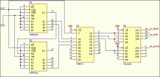
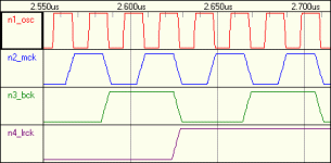
Here is the current iteration of this circuit. The buffer is included so that the rise time of the distributed clock is slower and to ensure Tlh=Thl. A 74HC241 will be used; the LS part is simply for simulation. Any criticism on this setup?
The timing is actually a little tight for worst-case, but I think the 74F logic will be quite sufficient. Looking at the timing diagrams more closely, the latch could probably be omitted, but I think this would open you up to a host of potential timing issues.
The timing is actually a little tight for worst-case, but I think the 74F logic will be quite sufficient. Looking at the timing diagrams more closely, the latch could probably be omitted, but I think this would open you up to a host of potential timing issues.
Attachments
Looks good to me, but I trust you for the different connections 😉. Just don't forget to ground unused inputs on the 373. Speaking of that, did you have particular reason for chosing a 373 (level triggered) instead of a 374 (edge triggered) ?
tiroth, can you give me your mail address ? (I can't help sending you a message from your web site....)
ftorres recently informed me via email that an 8 bit syncronous counter does in fact exist, the 74F269. This would be superior to the discrete solution.
- Status
- Not open for further replies.
- Home
- Source & Line
- Digital Source
- 'Proper' clock divider

