... things are moving ")
I am sitting at my desk, the schematics nearly ready to post here.
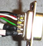
In the meantime, I can show you two details about the d-sub connector, used for the power supply (NEVER connect some computer devices to it
1. Bridge between pin 1 and 3
You can recognize the yellow isolated wire between pin 1 and 3. The purpose of this bridge, is to activate the switch on delay. The NE555 timer and the relay are not grounded, as long as no plug with this bridge is connected. As soon as you connect the plug, the delay count 20 to 30 seconds before delivering power for the LM3875's. Disconnecting the plug immediately switches of the power stage of the amp. Just for the sake of your speakers
2. How to connect thick cables to 9 pin D-sub
I inserted a thin piece of wire at the end of the thicker litz-wire and soldered it. Attach a piece of shrinking tube and you can solder it to the very small pins safely.
Next postings: the psu-schematic. Followed by a exact grounding and 9pin scheme within the next days.
Have fun!
Franz
dont forget: lethal voltages in this project!
I am sitting at my desk, the schematics nearly ready to post here.
In the meantime, I can show you two details about the d-sub connector, used for the power supply (NEVER connect some computer devices to it
1. Bridge between pin 1 and 3
You can recognize the yellow isolated wire between pin 1 and 3. The purpose of this bridge, is to activate the switch on delay. The NE555 timer and the relay are not grounded, as long as no plug with this bridge is connected. As soon as you connect the plug, the delay count 20 to 30 seconds before delivering power for the LM3875's. Disconnecting the plug immediately switches of the power stage of the amp. Just for the sake of your speakers
2. How to connect thick cables to 9 pin D-sub
I inserted a thin piece of wire at the end of the thicker litz-wire and soldered it. Attach a piece of shrinking tube and you can solder it to the very small pins safely.
Next postings: the psu-schematic. Followed by a exact grounding and 9pin scheme within the next days.
Have fun!
Franz
dont forget: lethal voltages in this project!
Attachments
Looking forward to the PS schematic.
... but just handdrawn. And Zang will have to review it (I think, Zang must be sleeping right now at this time).
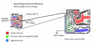
Here a draft from the grounding scheme, but from a "prototype" version. I will adapt it within the next days, as I feel very obliged now.
And I am really courious about all the new mini hybrid amps! Looking forward.
Franz
Attachments
Here we go: draft of part 1, including high current part, tube filament voltage and delay circuit. Part 2 coming soon.
Subject to be reviewed by Zang.
I plan to include the drawings (hopefully in better quality) in a pdf document to send it out.
Some comments:
1. Bypass caps for diodes
I did not draw them. They are optional, depending on your taste and diode type. On the board, you will find space for 8 caps parallel to D1 to D8.
2. Discharge resistors
Normally, they are not needed for LM-powerchips, as the chips itselfs are discharging them after switching of the amp. But with the remote PSU box, you can disconnect the cable and the caps are staying charged. So, better dont forget this resistors.
Franz
P.S.
I did not reduce the size of this drawing, otherwise you never could read my writing
Attachments
Franz G said:draft of part 1, including high current part, tube filament voltage and delay circuit
Franz... i had trouble readng bits of your map so this will need QC. I also don't think you meant to put 12.6V onto the filaments....
dave
Edit: map attached updated 27-oct-05
Attachments
Hi Dave
What a surprise! Many thanks.
I reviewed it, my result:
- add a primary fuse 1.6A slow for 220VAC
- Optionally, you can connect 8 caps in parallel to the diodes for the high current voltage
- the second caps in the high current part are just 1000uF.
- the rectifier in the filament part is a bridge type.
- the trimmer in the filament part has a value of 4.7k
- The trimmer for the NE555 is a 200k type
- between pin 3 and 4 of the NE555 is the relay coil for the delay connected.
Could you please correct your drawing and include the anode voltage part?
Would be great, when you could send it to me in high resolution:
franz.gysi at tiscalinet.ch, my spam account. Please add appropiate subject, so I can find the message.
Kind regards
Franz
Nearby perfect, Zang!
Many thanks.
For the first review, I just remark the voltage of the T2 is too high, resulting in a DC of +/- 117V.
I recommend about 45VAC for the tranny, resulting in +/- 63VDC, according to Duncans PSU Designer.
I leave now for work and will do a exact review this evening.
Franz
Many thanks.
For the first review, I just remark the voltage of the T2 is too high, resulting in a DC of +/- 117V.
I recommend about 45VAC for the tranny, resulting in +/- 63VDC, according to Duncans PSU Designer.
I leave now for work and will do a exact review this evening.
Franz
Franz G said:Could you please correct your drawing and include the anode voltage part?
Updated (i just replaced the drawing in the earlier post)
Would be great, when you could send it to me in high resolution:
What format? It is native to VectorWorks, but Illustrator, EPS, PDF, DXF, DWG & raster formats are all possible.
dave
digi01 said:your draw looks very clear
Yours is pretty good too
There should be no -6.3V on the filaments -- it should be 0 = ground (ECC88/6DJ8/6922 has 6.3V filament)
dave
planet10 said:
Yours is pretty good too
There should be no -6.3V on the filaments -- it should be 0 = ground (ECC88/6DJ8/6922 has 6.3V filament)
dave
Agreed. I don't see how they can get + & - voltage from a single bridge rectifier and single secondary x-former.
Franz G said:Now I have a dilemma: do I use the drawing from Zang for from Dave?
I decided, to use Zangs drawing.
Makes sense & not a problem for me. Mine was always intended as a take-off point for my own power supply which will not be quite the same.
dave
Very nice
I have just finished reading this thread; yery nice work from Digi01 and franz. There are so many nice projects to work on in here. It's really hard trying to decide wich one to make. I am In New zealand so i have to be very carefull when buying something as the dollar is not too good. How do these sound? I have completed one GC, but really like the look of this one.
Getting valves and accessories for this may be a real pain though. Will you be offering a slightly more comprehensive kit than just the boards?
GeWa said:The boards arrived today!
As always, they look very good.
Mine came yesterday...
What kind/brand of socket is intended? The holes are very small, and i have no hope of fitting any of the sockets i have into it, and the pads are so small i can't drill the holes out at all.
dave
- Status
- This old topic is closed. If you want to reopen this topic, contact a moderator using the "Report Post" button.
- Home
- Amplifiers
- Chip Amps
- Projects for next hollidays (the world smallest VBITNGC??)