Hi BillWojo,
Good job, we should also confirm if the top plate and central pole piece is of the same steel.
While the steel quality is not so important in the pot structure, the low iron content is still surprising.
Good job, we should also confirm if the top plate and central pole piece is of the same steel.
While the steel quality is not so important in the pot structure, the low iron content is still surprising.
https://tse2.mm.bing.net/th?id=OIP.z9JaKTE90P-Cj_NRfMPPCgDhEs&pid=15.1&P=0&w=300&h=300
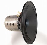
Here is a cross sectional view of the cast 808 driver that I have from an Altec spec sheet.
Looking at mine, I suspect that the throat piece is a zinc diecasting, it has that characteristic dull grey look about it. I'll know for sure once I get it apart.
Hentai, I know nothing about FEMM simulations. Does it allow you to simulate different alloy compositions? I'm wondering how much of a difference the slightly lower FE content is going to make in the magnetic circuit.
From the drawing, it looks like the center pole piece is the magnet and the phase plug sits on top and is centered by the throat piece.
I really need to get these apart and get measurements.
BillWojo
Wow, that link is poor quality. If you go to The Altec host board and look at the stickys at the top, there is a library of Altec professional products. There you can select pro drivers and the 808-8A spec sheet.
Last edited:
Hi,
The material surrounding the voice coil must have a high magnetic permeability so the it can "focus" the field through the voice coil. So it should be rich in iron.
Not sure with the 808 but the phase plug can be of steel on the outside and aluminum or non-ferrous material on the inside.
I can simulate many alloys in FEMM, it has a large library but we can also add different materials.
Hi Hentai, nice to see you. The throat piece is just the part that connects the pot to the phase plug and is surrounded by the alnico magnet as can be seen by the drawings.
Question. From all the pictures that I have seen of these dismantled, the cast pot looks to be about 50% thicker in the side walls of the pot and a bit thicker on the mounting flange side. Since the cast pot has a lot more metal in it, would that reverse the effect of having almost 1% less iron in it?
Thank you
BillWojo
Hi BillWojo,
I would say there won't be much of a difference between the two. Probably Altec made it so those designs are similar.
Either way it is difficult to say what would be better at this point.
I would say there won't be much of a difference between the two. Probably Altec made it so those designs are similar.
Either way it is difficult to say what would be better at this point.
Hi Hentai, I have the cast pot dismantled so I will probably just work with that one. I will make a sketch of the dimensions in the next day or so. Although I'm sure this was designed in the "inch" measurement system I will provide you with dimensions in mm rounded to the closest 0.1mm.
As I suspected, the internal port is a separate part made out of what looks like to be a zinc diecasting. It is surrounded by the alnico magnet that makes contact with both the bottom of the pot and the phase plug. I will get dimensions of all this.
BillWojo
As I suspected, the internal port is a separate part made out of what looks like to be a zinc diecasting. It is surrounded by the alnico magnet that makes contact with both the bottom of the pot and the phase plug. I will get dimensions of all this.
BillWojo
Hi BillWojo,
There must be some steel right on top of the alnico magnet that creates the magnetic gap. From the pictures I see it looks like it's either the entire phase plug or just the outer ring of the phase plug.
There must be some steel right on top of the alnico magnet that creates the magnetic gap. From the pictures I see it looks like it's either the entire phase plug or just the outer ring of the phase plug.
Hi Hentai, it's basically the entire bottom of the phase plug except where the non magnetic center core fits in. I sent you some pics via email, feel free to post them, I don't have a hosting site.
BillWojo
On Edit, look at post #672, there is a picture of the center piece. I believe it is a zinc die casting.
BillWojo
On Edit, look at post #672, there is a picture of the center piece. I believe it is a zinc die casting.
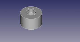
A little update for BillWojo and the 808 field coil conversion. BillWojo provided measurements of various parts of the driver and I was able to make a fem file. In the attached archive you can find it along with a stl file for central pole piece. This is a temporary design though so treat it as is.
We will refine the design more until a final version is ready but just wanted to share it here.
We will refine the design more until a final version is ready but just wanted to share it here.
Attachments
The driver looks just fantastic Hentai. I'm hoping to post pics and comments regarding my most recent efforts, soon. The cones, surrounds and baskets are finished, on to the spider this coming weekend... can't wait to hear my own babies do a little singing. 😉
Thank you and can't wait to see your progress as well.
By the way I made a tool that can help calculating the electric equivalent circuit for drivers. Please checkout the below link:
Project Ryu: Loudspeaker Electrical Model
By the way I made a tool that can help calculating the electric equivalent circuit for drivers. Please checkout the below link:
Project Ryu: Loudspeaker Electrical Model
gomper, I'm looking forward to seeing your work. I hope you took lots of pictures during the build, it was amazing watching Hentai's drivers as he designed and built them. I'm slowly working on a set of 802 field coil drivers myself, nothing near as difficult as what you guys did.
BillWojo
BillWojo
Hi Bill,
I sent you an email about the 808/802 conversion with the femm file. You can add it to the forums if you like to share.
I sent you an email about the 808/802 conversion with the femm file. You can add it to the forums if you like to share.
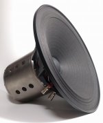
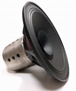
F144 based 12" drivers are pretty much done. You can check the datasheets and DIY files in the links below. I have 2 pairs available if anybody desires to purchase them assembled the price is 490USD/driver.
I am also attaching a picture of an upcoming 8 inch version.
F144/W Mid-Bass Datasheet:
http://projectryu.com/wp/wp-content/uploads/2017/06/Project-Ryu-F144W-Loudspeaker.pdf
F144/OB Full-range Datasheet:
http://projectryu.com/wp/wp-content/uploads/2017/06/Project-Ryu-F144OB-Loudspeaker.pdf
DIY Files:
https://github.com/Taur-Tech/Project-Ryu---Loudspeaker-Drivers/tree/master/Drivers/F144
If anybody tries the DIY and needs help you can always contact me.
Attachments
First of all, the drivers look wonderful Hentai. As always, congratulations on the accomplishment and thank you for being so generous with your work.
I have finally finished my first prototype - I was able to breath life into them about a month ago, and the most unexpected of things happened. They sounded amazing. Nobody is more surprised by that than I am.
I have gone radically off-script regarding the baskets. When I realized that I'd never build a basket so strong that I'd trust it to support the motors, I started thinking about them a different way - as materials contributing to the overall sound, like a musical instrument. Following that thought, I picked mahogany as my primary material and brass as a secondary material; mahogany is an excellent tone wood, and brass... well, brass just looks great. When they play music, you can certainly feel the sound vibrating through the wooden frame. Perhaps it makes a negligible difference in the character of the sound, but it pleases me to believe that it does.
The surrounds were a process of trial and error. I finally discovered the right lambskin leather for the job - it's paper thin, and wonderfully soft. I dyed it matte black with leather dye, and soaked and shaped it over a sealed hydrocal mold form.
The cones were a longer process of trial and error - I must have made 30 or more versions. The current main cone utilizes three layers of washi - two kinwashi layers as the backing, and a nice hosho paper as the facing layer. The whizzer incorporates two layers, omitting a layer of kinwashi. I rushed a bit through the molds they both were pulled from - but I know I can get a very clean result with carefully cast molds the next time around.
The voice coil is a little over 9 Ohms - 36mm, 44 windings of .1426mm copper wire. The former is an Okawara washi and it's doing a perfectly good job - but I'll likely make it from a single layer of hosho for the next version, and dial down the windings to get about an 8 Ohm result.
When I read the suggestion from tinnitus regarding using threads for the spider assembly, I was sure that was what I'd try the first time around. The spider is a light, very thin silk cord material wound around brass binding posts and secured to the former with a little epoxy. I love it - the suspension is stable but soft, and creating them is quick and painless. I am led to believe that silk can easily handle use over the years... hopefully I'm not misinformed.
The entire moving mass (surround, main/whizzer cones, voice coil and spider) comes in at 16.5 grams.
I've been running them with the bench power supplies at 1.2 amps / 9 volts and so far, they have remained acceptably cool when run for 15 continuous hours. Quite hot to the touch by then, but nothing crazy. Something strange happens over time, however - I am hoping the wonderfully intelligent people in this thread can explain it to me:
Over time, one power supply holds a steady 9 volts but the amps slowly go down in value, and settle down eventually at about 1.2 amps. The other power supply maintains a steady 1.2 amps, but the volts slowly increase and eventually settle at about 9.4 volts. It happens slowly over several hours Why? Is it something I can solve with more precise construction of the motors or moving assembly?
I have yet to make the phase plugs, but I'll be milling those out of mahogany as well, very soon.
This arrived in the mail yesterday...
Dayton Audio Dayton Audio Test System | DATS
...and I'll be measuring the T/S parameters this evening. Excited to begin the cabinet design this weekend, and to see how I'm looking with the frequency response.
Below are a few pics of the works in progress, followed by a video showing them playing a song through for the very first time the evening I finally powered them up. The only things playing are those drivers in free space sitting on the floor - the other speakers in the room aren't connected. Can't wait to hear them perform in a suitable pair of cabinets.
Thanks again to all, I'll post my T/S and frequency response measurements this weekend.
A surround drying:

Basket and motor:

Spider assembly:

Ready to glue the assemblies to the baskets and trim off waste:

Finally, playing a first song all the way through:
http://kensonger.com/drivers_v1.html
Cheers.
I have finally finished my first prototype - I was able to breath life into them about a month ago, and the most unexpected of things happened. They sounded amazing. Nobody is more surprised by that than I am.
I have gone radically off-script regarding the baskets. When I realized that I'd never build a basket so strong that I'd trust it to support the motors, I started thinking about them a different way - as materials contributing to the overall sound, like a musical instrument. Following that thought, I picked mahogany as my primary material and brass as a secondary material; mahogany is an excellent tone wood, and brass... well, brass just looks great. When they play music, you can certainly feel the sound vibrating through the wooden frame. Perhaps it makes a negligible difference in the character of the sound, but it pleases me to believe that it does.
The surrounds were a process of trial and error. I finally discovered the right lambskin leather for the job - it's paper thin, and wonderfully soft. I dyed it matte black with leather dye, and soaked and shaped it over a sealed hydrocal mold form.
The cones were a longer process of trial and error - I must have made 30 or more versions. The current main cone utilizes three layers of washi - two kinwashi layers as the backing, and a nice hosho paper as the facing layer. The whizzer incorporates two layers, omitting a layer of kinwashi. I rushed a bit through the molds they both were pulled from - but I know I can get a very clean result with carefully cast molds the next time around.
The voice coil is a little over 9 Ohms - 36mm, 44 windings of .1426mm copper wire. The former is an Okawara washi and it's doing a perfectly good job - but I'll likely make it from a single layer of hosho for the next version, and dial down the windings to get about an 8 Ohm result.
When I read the suggestion from tinnitus regarding using threads for the spider assembly, I was sure that was what I'd try the first time around. The spider is a light, very thin silk cord material wound around brass binding posts and secured to the former with a little epoxy. I love it - the suspension is stable but soft, and creating them is quick and painless. I am led to believe that silk can easily handle use over the years... hopefully I'm not misinformed.
The entire moving mass (surround, main/whizzer cones, voice coil and spider) comes in at 16.5 grams.
I've been running them with the bench power supplies at 1.2 amps / 9 volts and so far, they have remained acceptably cool when run for 15 continuous hours. Quite hot to the touch by then, but nothing crazy. Something strange happens over time, however - I am hoping the wonderfully intelligent people in this thread can explain it to me:
Over time, one power supply holds a steady 9 volts but the amps slowly go down in value, and settle down eventually at about 1.2 amps. The other power supply maintains a steady 1.2 amps, but the volts slowly increase and eventually settle at about 9.4 volts. It happens slowly over several hours Why? Is it something I can solve with more precise construction of the motors or moving assembly?
I have yet to make the phase plugs, but I'll be milling those out of mahogany as well, very soon.
This arrived in the mail yesterday...
Dayton Audio Dayton Audio Test System | DATS
...and I'll be measuring the T/S parameters this evening. Excited to begin the cabinet design this weekend, and to see how I'm looking with the frequency response.
Below are a few pics of the works in progress, followed by a video showing them playing a song through for the very first time the evening I finally powered them up. The only things playing are those drivers in free space sitting on the floor - the other speakers in the room aren't connected. Can't wait to hear them perform in a suitable pair of cabinets.
Thanks again to all, I'll post my T/S and frequency response measurements this weekend.
A surround drying:
Basket and motor:
Spider assembly:
Ready to glue the assemblies to the baskets and trim off waste:
Finally, playing a first song all the way through:
http://kensonger.com/drivers_v1.html
Cheers.
Last edited:
Over time, one power supply holds a steady 9 volts but the amps slowly go down in value, and settle down eventually at about 1.2 amps. The other power supply maintains a steady 1.2 amps, but the volts slowly increase and eventually settle at about 9.4 volts. It happens slowly over several hours Why? Is it something I can solve with more precise construction of the motors or moving assembly?
Heat = resistance. Are you sure both amps are identical? Sounds like one is constant voltage and current sags with added resistance and the other bumps the voltage to try to maintain constant current.
I may be way off, but if it takes hours to manifest and takes hours to warm up the power supplies it seems a fair guess.
Also that's really amazing work you're doing there. I sure hope you're happy with the results for all the effort you have put into this project.
Thanks so much for the kind words and feedback, guys. Here are the T/S parameters and impedance response from the weekend. Thoughts appreciated - I feel like I should be happy, but I have a limited understanding of how to insightfully interpret the results. Need to find a good, cheap PC program for measuring the frequency response... I'll share that soon as well. Cheers.
Piston Diameter: 8.543 inches (217mm)
SPL: 94.36 dB 1W/1m
R(e): 9.216
F(s): 19.51
Q(ts): 0.2242
Q(es): 0.2389
Q(ms): 3.656
L(e): 0.4473
M(md): 17.5 grams
M(ms): 22.5 grams
V(as): 20.05 cubic feet (567.8 liters)

Piston Diameter: 8.543 inches (217mm)
SPL: 94.36 dB 1W/1m
R(e): 9.216
F(s): 19.51
Q(ts): 0.2242
Q(es): 0.2389
Q(ms): 3.656
L(e): 0.4473
M(md): 17.5 grams
M(ms): 22.5 grams
V(as): 20.05 cubic feet (567.8 liters)
- Home
- Loudspeakers
- Multi-Way
- Project Ryu - DIY Field Coil Loudspeaker