Hi,
I've started to develop a programmable active analogue crossover. The board has an onboard PIC chip for easy programming via a Windows app / USB. The initial goal is to see if I can recreate the Linkwitz ASP in a programmable analogue form for the LX521 speakers. The signal path is completely differential analogue from in to out. No DSP in sight.
I am designing the board to use with 8 of the MOD86 amps by Tom/Neurochrome.
http://www.diyaudio.com/forums/vend...mposite-amplifier-achieving-0-0004-thd-n.html
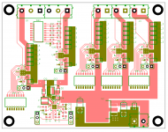
So, I have made a start. I have started the schematic, chosen a few comps, and made a simple PCB layout.
Input - XLR differential (OPA1632) to 0-3v.
Output - 0-3v differential to differental / single ended (OPA1632&OPA1611)
Analogue and digital supplies - TPS7A47/33
Crossover ICs = special sauce.
I am looking at resitors and cap choices. I hear Susumu RG 0805s are the gotos for SMD. I will keep you updated over the course of the next few weeks.
I've started to develop a programmable active analogue crossover. The board has an onboard PIC chip for easy programming via a Windows app / USB. The initial goal is to see if I can recreate the Linkwitz ASP in a programmable analogue form for the LX521 speakers. The signal path is completely differential analogue from in to out. No DSP in sight.
I am designing the board to use with 8 of the MOD86 amps by Tom/Neurochrome.
http://www.diyaudio.com/forums/vend...mposite-amplifier-achieving-0-0004-thd-n.html
So, I have made a start. I have started the schematic, chosen a few comps, and made a simple PCB layout.
Input - XLR differential (OPA1632) to 0-3v.
Output - 0-3v differential to differental / single ended (OPA1632&OPA1611)
Analogue and digital supplies - TPS7A47/33
Crossover ICs = special sauce.
I am looking at resitors and cap choices. I hear Susumu RG 0805s are the gotos for SMD. I will keep you updated over the course of the next few weeks.
Attachments

While using a PIC will make it possible to simultaneously implement many changes to the crossover at the same time, what I didn't see mentioned is HOW you plan to make the changes to the analog active circuits. This is really not a trivial matter in my eyes if you want the performance of the crossover to be predictable and accurate compared to what you "dial up" on the PIC.
Typically you are talking about circuits with active elements (e.g. op amps) and networks of resistors and capacitors. These latter two passive components are pretty much all you can change, and of these digital potentiometers can make for good control elements. The only problem with these is the lack of good precision. Sure you can precisely set the end-to-end resistance to step 512 of 1024 but the end-to-end resistance of each device might be +/-20%. Will you calibrate all of them?
What will your approach be for changing the performance of the filters in the crossover and what topology(ies) will you be using? You mentioned some special sauce or whatever. Please give more details on your ideas.
I looked into this kind of thing a few years ago (several years ago) and gave up. Now I just do everything using DSP in software, where I can implement and control more filters than I could possibly even use in a loudspeaker (well IIR filters at least). I don't feel a need for a regression to a complicated analog system, so I am curious about what motivated you to launch this effort. Do tell. Not trying to discourage you, just curious whether some advances in technology has made some things possible that were not (or not at all easy to do) in the past.
Last edited:
Thanks Charlie. I'll try and answer your questions in the coming days. I've not seen the IC used before on DIY audio. I don't know whether that is a good or bad thing...
I'll second the emphasis on switching / control devices. Yes, DPOTs and programmable attenuators can be used to control a filter, but relays are often easier to use with standard filter circuits. To change the frequencies, sometimes it's difficult to use only a programmable attenuator - an actual switch whose switching channel can float without creating distortion is needed, for example to change the value of a cap that has a nonzero signal on both terminals. That nixes DPOTs and solid state switches, as they behave well only within a narrow signal voltage range, or with almost zero voltage at the switching terminals.
As for your component choices, the Susumu 0805 resistors are quite nice, quite stable, and very inexpensive. Great choice.
Capacitors are a tougher choice. Since you're using SMD, I'd like to recommend the modern NP0/C0G multi layer ceramic caps. They're made from an extremely linear dielectric (calcium zirconate), they have no microphonic effects and no nonlinearities. The problem is that they're only available up to 0.1µF or possibly 0.22µF. For larger values, you have to parallel multiple devices. But, they are actually better than film caps, since their terminations are far more reliable - there are no 'bad units' that can cause measurable distortion, which is what one sees in anywhere from a few bad units to maybe 20% of a batch of otherwise quality film caps.
If you'll use through-hole films, then it's hard to recommend anything specific, as the unit to unit defects mentioned above are essentially their largest problem. The traditional thinking is that by choosing a nice dielectric, a good cap is assured, but that doesn't always happen in practice. To avoid these termination defects, some sort of screening procedure should be done on each unit, either to look at ESR (which points to termination quality) or dissipation factor, which could also point to similar problems.
A test using a high res distortion analyzer will also work, but the only commercial analyzer I know of with a distortion floor low enough to measure this problem in a cap is the APx-555. It's a fantastic analyzer, but it's very pricey. There are some DIY generator - analyzer combos out there that can approach or beat the 555 residual, but you'll have to do a lot of work to cobble a fixed frequency oscillator and notch filter together. But, amazingly enough, with an HD residual below -150dBC, you can detect capacitor defects that cause distortion on a unit by unit basis.
Good luck with your project, and try to tackle the biggest problem - the switching issue - before you sweat the details of specific components. It's not a simple problem to solve!
Many thanks Monte. Still working hard on the project. I've decided to build my own PSU module with many output voltage options. It's a fairly useful device with screw terminals for in/outs.
Firstly I'm using an LM1085 to create a 5V rail.
For bipolar supply - ADP5070 5v to +/- 15V with TPS7A47/33 LDOs / dip switch outs.
For +ve rails = 3x TPS7A47 with dip switch outs.
Firstly I'm using an LM1085 to create a 5V rail.
For bipolar supply - ADP5070 5v to +/- 15V with TPS7A47/33 LDOs / dip switch outs.
For +ve rails = 3x TPS7A47 with dip switch outs.
Attachments
Last edited:
I have used the PIC in numerous audio systems.
Speaker protect, USB mixer control, irs2092 power supply fail reset circuit etc etc.
I came a cropper with the USB mixer. I naively just mixed in the power supply circuit with the audio. With inputs shorted I was getting 1 volt 50Hz hum on the output !
The charging impulses into the smoothing capacitors was modulating the ground and getting into the audio signal.
I re-laid out the pcb with power supply totally separate and it worked a treat.
You could connect your system using a PIC18F4550 USB and control it from your PC.
I picked up the basic circuit and software for PC and PIC from Home - WFFwiki
Anadigm?
I assume you are referring to the Anadigm AN231E04 for your "special sauce". I had looked at their first generation of FPAA chips many years ago, but dismissed them when I couldn't find stock in the large suppliers. The AN231E04 is their 3rd-generation part, so they have continued to invest, and they have continued to evolve their design tools. Arrow has stock of the chips at a reasonable price ($13). This looks like a good solution to the problem you are trying to solve. There is a nice briefing on the company here.
Around the same time I was looking at Anadigm, I tried the digital potentiometer approach that Charlie touched on. There is a thread on that design here. It works and is quiet, but it lacks the flexibility of the analog arrays, and it takes up a lot more space. Also, the cost adds up rather quickly, as the low distortion digital pots are several dollars apiece.
About active analog crossover (a bunch of ops), could it have
group delay trimming
time alignment trimming
phase trimming (if we have to avoid those digital xos)?
group delay trimming
time alignment trimming
phase trimming (if we have to avoid those digital xos)?
Hey Mtoc, there is no analogon to time, flowing like a river, so it cannot become introduced by analogue means. About what is possible analoguely, apart from minimum-phase filters, phase can be further distorted; most crossovers are already allpasses. Allpasses of second order (having phase of some fourth order hi-/passes) may also introduce group delay peaks. (I think, a first-order allpass cannot, because i think, it has phase of a hi-/lopass with Q=1/2, while in order to peak group delay one needs a resonance, say Quality greater than 1/2.)
For a variable slope phono pre i used the Analog Devices switches, almost went blind soldering the bXggers. They are very low THD if driving another opamp, and very quiet.
I just used Linear Tech's version of the Arduino, Linduino as i could program it on the fly.
WRT caps, the new ceramics appear to be the way to go. Scott Wurcer describes a bridge measurement system in the most recent issue of Linear Audio
I just used Linear Tech's version of the Arduino, Linduino as i could program it on the fly.
WRT caps, the new ceramics appear to be the way to go. Scott Wurcer describes a bridge measurement system in the most recent issue of Linear Audio
The signal path is completely differential analogue from in to out.
Fully differential signalling is a commendable goal, but passive parts tolerances in your analog filters will make matching +/- legs rather difficult, especially with selectable values.
The Mod-86 amps are actually single ended amps, with a BAL/SE converter added to the front end. THAT1200 will accept SE signal without any problem, or you can skip the differential input on Mod86 and go straight to the LM49710's SE input via the THAT1200 output pad on PCB.
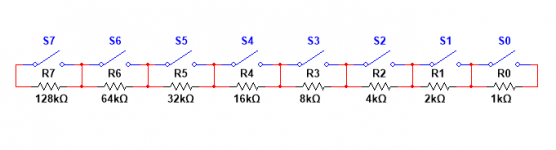
For a variable slope phono pre i used the Analog Devices switches,
You can get a lot of values, and a lot of precision with these type arrangements:
Attachments

My experience with my crossover is that this is more like a tool than a xover sitting beside the amps on the self for 20 years untouched.
- Home
- Source & Line
- Analog Line Level
- Programable Active Analogue Crossover