I copied this schematic off of an ATX power supply, it's the stand-by circuit.
The transformer is a 1 primary, 1 feedback on the same side and one center tapped secondary.(I didn't have the right symbol in my program so I stuck two together)
Only other thing I notice was on the board they had a spot of a resistor going for the emitter of 2SC3150 to base of 2SC945. Any ideas what that mite of been for?
Attachments
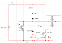
Someone might comment on this if you show the transformer inductances or turns ratios. Further, the 103 and 151 caps don't make sense.
151 is 15 +1 zero (0) so 150pF
103 is 10 +3 zero (0) so .010uF or 10nF
transformer inductance is: Feedback is 5.5uH, Primary is 4.42mH
btw most ceramic disc capacitors have the marking like 104, 103 things like that just in case you weren't sure.
103 is 10 +3 zero (0) so .010uF or 10nF
transformer inductance is: Feedback is 5.5uH, Primary is 4.42mH
btw most ceramic disc capacitors have the marking like 104, 103 things like that just in case you weren't sure.
It looks like a self-oscillating switcher, not very efficient but cheap. I've seen a 25-watter using that scheme.
Only other thing I notice was on the board they had a spot of a resistor going for the emitter of 2SC3150 to base of 2SC945. Any ideas what that mite of been for?
it is used to limit the base drive to the chopper trannie, you shouild use that.😀
- Status
- Not open for further replies.