My product is so flexible, that it's up to you how you will use it. The AC section (either transformer, or AC receptacle) can be easily trimmed off, if it does not suit your needs. You can also put two fuses (on hot and on neutral, if you wish). I'm offering compact integrated solution, which btw complies with safety regulations, but it's completely up to end user how he will implement the board and use its features.
There is no set rules as how it supposed to be done, there is only a set of options. But most of you, participating in this discussion, missed to understand that.
There is no set rules as how it supposed to be done, there is only a set of options. But most of you, participating in this discussion, missed to understand that.
Peter, since you have increased the standoff length, can I assume there is space, for those that want to, to use a fused IEC connector as I previously mentioned? At least there are several options available then for each to implement as they see fit.
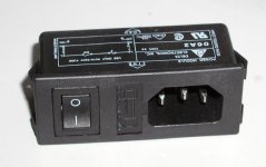
Here's another solution. Nobody says that place on my board, specified for AC connection has to be used. I made it there, as it works for me and offers compact, one piece assembly, without need for a chassis ar any wires.
But this Power Module, that I've been using on all my amps and PS, can be easily implemented with a DAC board, by simply connecting it with wires to transformer pins (on the bottom).
But this Power Module, that I've been using on all my amps and PS, can be easily implemented with a DAC board, by simply connecting it with wires to transformer pins (on the bottom).
Attachments
Vikash said:Peter, since you have increased the standoff length, can I assume there is space, for those that want to, to use a fused IEC connector as I previously mentioned? At least there are several options available then for each to implement as they see fit.
You see, the standoff length, or the material, was never specified here. One can use any suitable length, (as one can use non metal materials). This gives you freedom to arrange for any required clearance to comply with any local safety regulations.
I don't understand why it needed few pages of a thread to get it through. Obviously, some may have other agenda, than just the safety issues.
So in other words, the space for any fused IEC connector can be easily created. Some people assume that PC board can only be populated with parts in top layer, but to me, it was always obvious that both layers can be used with good effect, the only requirement is the space.
Yes, there are countless options, and one can do whatever he feels is optimal.
I agree. There's nothing to stop someone from putting in a Fused IEC connector or any number of other arrangements ( a fuse inline on the cable going to the board). I would most definitely do it that way, anyhow, since I like my fuses closest to the point of power entry as I can get them.
I do recall a reader writing in to Audioxpress regarding one of their articles that there is some specific distance that mains AC must be from the sections powered by the secondary. Someone in the know wrote a scathing letter about some other guy's project PCB that evidently violated numerous safety protocols (if I recall, he had a 120/240V trace very close to some 5V traces that went to a USB port to turn on the amp). I don't see anything remotely like that on Peter's board, though.
It would be cool if there was some FAQ or something on PCB design for line-powered equipment, though. Then all the newer folks who are picking up PCB design would have someplace to reference these types of things should their design turn into a prodcut, and should they want to get it certified.
Sorry, I'm not trying to go off topic, it's just a thought that came to mind from all the discussion on this subject.
Peter,
the SE boards arrived two days ago. They look awesome and I'm looking forward to equipping them. Cheers!
Best regards,
Oliver
the SE boards arrived two days ago. They look awesome and I'm looking forward to equipping them. Cheers!
Best regards,
Oliver
Sorry, no other agenda than your customers safety. I'm pretty sure that you haven't told those poor 230 volt guys about mounting conditions unless we hadn't pointed it out.Peter Daniel said:Obviously, some may have other agenda, than just the safety issues.
Believe it or not I do care about the output from you and Brian and if you have made obvious errors or there are room for important improvements, why not tell you about it? Remember the grounding issue for the LM3875 board which is fixed now?
peranders said:
Sorry, no other agenda than your customers safety. I'm pretty sure that you haven't told those poor 230 volt guys about mounting conditions unless we hadn't pointed it out.
Believe it or not I do care about the output from you and Brian and if you have made obvious errors or there are room for important improvements, why not tell you about it? Remember the grounding issue for the LM3875 board which is fixed now?
Peranders,
You are not in position to discuss this board design without closely examining it. Suggesting that there are erors, whithout seeing it (or testing for that matter) is not appropriate.
If you want to continue this discussion, you can do it by pm, but any further posts of yours with regards to AC aspects of this particular board will be removed, inluding most recent one.
You can of course discuss the DAC, if you wish.
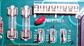
To put end to the crippage discussion, here's a picture of AC section of a Madrigal preamp. As you can clearly see, the distance between hot an neutral connection (on the board) is less than 2mm. This preamp is approved to work with 230V.
My board is much better in that regard, and I will not accept any further comments, in this thread, with regards to crippage conditions; you either know what you are talking about, or not talk at all.
My board is much better in that regard, and I will not accept any further comments, in this thread, with regards to crippage conditions; you either know what you are talking about, or not talk at all.
Attachments
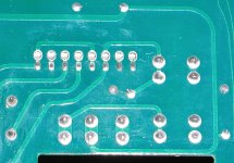
Few more comments after examining ML board. The "Live" terminal is only 1.3mm away from a trace coming from Earth ground terminal. This terminal is further connected to the chassis, and by 10 ohm resistor to the ground plane.
We are talking about 230V connected trminal, being separated by 1.3 mm distance from a trace leading to a ciruit's ground plane, all this before the fuse.
If there were any doubts, I am beginning to believe that I am much better manufacturer than Madrigal.😉
Here's the pic of bottom layer fm ML380 preamp.
Attachments
Peter, I think you are overreacting a bit. I was talking more in general when I mentioned "errors". The issue is lifted up I think. That's good.Peter Daniel said:You are not in position to discuss this board design without closely examining it. Suggesting that there are erors, whithout seeing it (or testing for that matter) is not appropriate.
Your pcb isn't deadly dangerous, in fact rather OK, but it may have some "issues". It's a big difference.
Peter, have you ever asked yourself: "How should I do so the picky europeans would be happy?"
Regarding your pictures, I'm pretty certain that this gear wouldn't be approved in Europe if it really was tested by swedish Semko, german TüV etc. Years back I worked in a hostital and checked eqiupment. In those days equipment for "professional use", "lab use" etc. didn't have to have ANY approvals. Boy, I have seen a lot, especially american products which electrical parts only approved for 120 V sold in Europe.
I just want to tell you that the proofs you have given here by the pictures isn't any proof really how things should look like in Europe.
So far noone has argued against me so this will mean I'll suppose that I'm right or at least close to the truth.
ML38 was the most successfull Madrigal product, selling in excess of 4,000 in 1996. It was sold all over the world.
If those pictures are not enough for you, I don't know what would be. Probably only report from Swidish Semko.😉
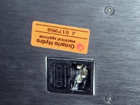
This board is 230V approved, as you see it has a special socket, for voltage setting. This is also stated in service manual, that I have.
In this thread, try to refrain from making claims "in general". Whenever you make a claim, I would expect supporting evidence.
After all, we are not discussing the sound of wire here.
If those pictures are not enough for you, I don't know what would be. Probably only report from Swidish Semko.😉
This board is 230V approved, as you see it has a special socket, for voltage setting. This is also stated in service manual, that I have.
In this thread, try to refrain from making claims "in general". Whenever you make a claim, I would expect supporting evidence.
After all, we are not discussing the sound of wire here.
Seeing pictures isn't enough for I'm afraid. If the amp/CD has some trustworthy approval markings at the back I would be more confident.
peranders said:Seeing pictures isn't enough for I'm afraid. If the amp/CD has some trustworthy approval markings at the back I would be more confident.
Let's put approval markings aside.
It is 1.3mm distance between 230V terminal (direct connection from AC receptacle) and the trace connected to the circuit's ground plane. The ground plane covers most of the board's area and the fill has 15 mil spacing from the components pads.
In the light of previous creepage discussion, and concerns mentioned by Peranders (and some others supporting him), I can't uderstand how this (Madrigal) design could see the daylight.
Is anybody willing to explain it?
Turn the question around: What does your electrical standard say?Peter Daniel said:In the light of previous creepage discussion, and concerns mentioned by Peranders (and some others supporting him), I can't uderstand how this (Madrigal) design could see the daylight.
Is anybody willing to explain it?
Ontario Hydro, some kind of recognized testing institute?
Peter, don't forget that I'm on your side.
Peranders, what do you really want to accomplish?
First, you question if I used a fuse. When you finally found it, you question if the creepage on board is according to safety regulations.
When I show you an example, where AC interface has substantialy more inferior specifications than my board, yet it was approved by the electrical safety agency available in my area, you question the status of that institution (BTW, this unit was approved by every other local agency, as it was sold in all Eropean countries and all over the world).
So now you want me to come to Sweden and test everything with Semco?
If you want to know what my electrical standard say, find it yourself, as I don't see a need to explain myself to you any longer.
For me, this discussion has ended.
Maybe this will help to put the whole thing to rest:
http://www.ce-mag.com/ce-mag.com/archive/01/03/ProductSafety.html
http://www.ce-mag.com/ce-mag.com/archive/01/03/ProductSafety.html
Originally posted by peranders
Turn the question around: What does your electrical standard say?
Ontario Hydro, some kind of recognized testing institute?
Ontario Hydro is the Provincial Electric Power Utility. At the time that that preamp was manufactured, Ontario Hydro's R&D laboratory and testing facility was a widely certified approval test agency, authorized to perform certifications for CSA, UL, CE, TuV, JIS, MIL-SPEC, and many many others. Unfortunately, that section was privatized a few years ago and I don't believe they are still providing the same certification services.
Cheers, Terry
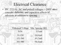
http://power.ece.uiuc.edu/Balog/images/PCB Basics.pdf
page 42
(P.S. Does ML380 have three fuses in the transformer primary????)
page 42
(P.S. Does ML380 have three fuses in the transformer primary????)
Attachments
- Status
- Not open for further replies.
- Home
- Amplifiers
- Power Supplies
- Products certifications, safety requirements (and creepage distance)