Hello!
This is my first post. I made a lm386 mini amp as my first project and I just began my second project to create a clone of proco Rat.
I chose the schematic from electrosmash.
ElectroSmash - ProCo Rat Analysis
I recreated the circuit on a breadboard but it didn't work. So after a lot of tests I found that if I connect the input to the pin 6 there was an output and the Volume and Tone knobs were working. So the Clipping stage doesnt seem to work. Checked the Voltage between the 7 and 4 pin and its a little less than the battery Voltage (because of the 47 ohm resistor connected to 9v Main).
Can anyone help debug this circuit?
There is the issue.
Pins 2 & 3 must sit at the 4.5 volt point or virtual ground.
I would see what voltage you have on the centre point between the two 100k resistors, it must be half battery voltage which is ~4.5 volts.
Pins 2 & 3 must sit at the 4.5 volt point or virtual ground.
I would see what voltage you have on the centre point between the two 100k resistors, it must be half battery voltage which is ~4.5 volts.
You must have the same voltage on pin 3.
If pin 6 goes above pin3, then pin 2 corrects the voltage.
If you have ~1.8v on pin 2/3 then there is an issue with the chip. Is pin 1&8 connected to anywhere other than the 30p Cap? Check your tracks.
If pin 6 goes above pin3, then pin 2 corrects the voltage.
If you have ~1.8v on pin 2/3 then there is an issue with the chip. Is pin 1&8 connected to anywhere other than the 30p Cap? Check your tracks.
Pin 1 and 8 are only connected with a 33pF capacitor. (I dont think it will make big difference).
I also changed the cap C6 with a 1uF and the R5 with a 3.3K (as I understand this changes the frerquencies that are muted from 60Hz to 48Hz) and the C1 and C9 caps with 10 nF caps.
I also changed the cap C6 with a 1uF and the R5 with a 3.3K (as I understand this changes the frerquencies that are muted from 60Hz to 48Hz) and the C1 and C9 caps with 10 nF caps.
Update: Im measuring 0V between ground and pin 2 3 and six. Still not working though. And I found out that if I connect the inpu to pin 2 I get an output but it sounds like it passes through a low pass filter. Any suggestion or tip?
Yes, it will NOT work if pin 2, 3, 6 are all at zero volts. No surprise there. 🙁Update: Im measuring 0V between ground and pin 2 3 and six. Still not working though.
Firstly, you MUST get half (or nearly half) of the battery voltage at pin 3. Measure from the junction of R11/12 to ground - you should get half battery voltage there (nominally 4.5 volts). Measure across C13; you should get the same 4.5 volts. Measure at both ends of R2 (to ground) - you should get 4.5 volts at both ends. Measure at both ends of R3 - you should get 4.5 volts at both ends. Measure across C3 - you should get 4.5 volts. And when you have got this far, you will now have 4.5 volts at pin 3.
If one of the above steps didn't give you 4.5 volts, there's your clue - the wrong voltage will pinpoint the mistake you made, or the bad component you have. Find and fix, then continue with the measurements above, until you finally have 4.5 volts (or slightly less, depending on your DMM) at pin 3.
When you get this far, post again. There is no point trying anything else until you get half of the battery voltage at pin 3.
-Gnobuddy
Are you sure that I must measure 4.5 Volts at both R2 ends? At the one end that is directly connected to the 4.5V I measure about 4.5V. But at the other end I measure about the half 2.25V.
Are you sure that I must measure 4.5 Volts at both R2 ends? At the one end that is directly connected to the 4.5V I measure about 4.5V. But at the other end I measure about the half 2.25V.
R2 is 1Meg. If your meter is also 1Meg, then indeed it is 4.5V when you are not poking, and sags to 2.25V when you poke it.
If one side of C7 is 4.5V then likely the R2 voltage is fine.
I suspect C2 is shorted.
To clarify PRR's comment, most DMMs now have a 10 meg input resistance; using one of these, you will measure not exactly 4.5 V, but 4.09 volts, at the lower end of R2 (the end connected to C1).
If you have a very old, or very poor quality DMM, it might have a 1M input resistance, which causes severe errors in reading voltages in circuits like this one. In this case, a 50% error, reading 2.25 volts when the actual voltage is 4.5 volts.
Are you seeing 2.25 V on pin 3, or only on the lower end of R2?
If the latter, PRR suggests C2 is shorted. Another possibility is that R3 is not making contact at one or both ends.
Once you fix the mistake, you should have 4.5 volts on all three of pins 3, 6, and 2.
-Gnobuddy
If one side of C7 is 4.5V then likely the R2 voltage is fine.
C7 has 0 Volts at both its ends.
I suspect C2 is shorted.
I changed the C2 with another capacitor. No output
If you have a very old, or very poor quality
Yes my multimeter is cheap I bought it like 5 euros.
I rechecked R3.Are you seeing 2.25 V on pin 3, or only on the lower end of R2?
If the latter, PRR suggests C2 is shorted. Another possibility is that R3 is not making contact at one or both ends.
Yes I measure 2.25 at pin 3. At pin 2 and 6 i measure 0Volts. If i mistakenly touch both pin 2 and 3 with my probe I measure voltage at both pin 2 and 6 but it is constantly decreasing until it reaches 0 V.
Thanks everyone in advance for their time!!!
I've used $5 DMMs that had 10M input impedance - price alone is no guarantee that you have a 1M input impedance.
Google the DMM model and make you have, and find the manufacturer's datasheet. Look for input resistance or input impedance on the volts range.
You need to know if you can trust the meter, otherwise you're working blind - there's no point measuring voltages if the meter is introducing a 50% error. Even if you find out that the meter only has 1M input resistance, you can still make sense of the results with a little math. But if you have no idea what the input resistance is, every measurement is a crap-shoot, and cannot be trusted.
1) Check voltage at pin 4. Should be zero volts. Fix if not.
2) Check voltage at pin 7. Should be 9 volts (battery voltage.) Fix if not.
3) Make sure C3 is connected between pins 1 & 8.
4) Set distortion pot to minimum. Measure resistance between pins 2 & 6. Should be low, maybe few hundred ohms. Fix if not.
5) Temporarily remove C5 & C6.
Voltage on pins 6 & 2 should be half battery voltage now. If not, the op-amp is probably dead.
If voltage on pins 6 & 2 is now correct (4.5 V), replace C5. Check voltages on pins 6 & 2 again. Not correct? Throw away leaky C5, replace with a good cap instead.
Voltages on 6 & 2 correct now? Replace C6. Voltages not correct? Throw away leaky C6, replace with good cap. Voltages correct? Done.
The voltage falls with time because your meter is discharging C5 and C6 through itself. This doesn't tell us anything useful by itself. But it is inconsistent with your measurement that there is zero volts at pin 6 - the only way C5 / C6 can charge up to anything is if pin 6 is NOT at zero volts.
-Gnobuddy
Google the DMM model and make you have, and find the manufacturer's datasheet. Look for input resistance or input impedance on the volts range.
You need to know if you can trust the meter, otherwise you're working blind - there's no point measuring voltages if the meter is introducing a 50% error. Even if you find out that the meter only has 1M input resistance, you can still make sense of the results with a little math. But if you have no idea what the input resistance is, every measurement is a crap-shoot, and cannot be trusted.
There are only 7 pins to that op-amp, how hard can this be?Yes I measure 2.25 at pin 3. At pin 2 and 6 i measure 0Volts.
1) Check voltage at pin 4. Should be zero volts. Fix if not.
2) Check voltage at pin 7. Should be 9 volts (battery voltage.) Fix if not.
3) Make sure C3 is connected between pins 1 & 8.
4) Set distortion pot to minimum. Measure resistance between pins 2 & 6. Should be low, maybe few hundred ohms. Fix if not.
5) Temporarily remove C5 & C6.
Voltage on pins 6 & 2 should be half battery voltage now. If not, the op-amp is probably dead.
If voltage on pins 6 & 2 is now correct (4.5 V), replace C5. Check voltages on pins 6 & 2 again. Not correct? Throw away leaky C5, replace with a good cap instead.
Voltages on 6 & 2 correct now? Replace C6. Voltages not correct? Throw away leaky C6, replace with good cap. Voltages correct? Done.
What does "I measure voltage" mean? How many volts do you measure at pins 2 & 3?If i mistakenly touch both pin 2 and 3 with my probe I measure voltage at both pin 2 and 6 but it is constantly decreasing until it reaches 0 V.
The voltage falls with time because your meter is discharging C5 and C6 through itself. This doesn't tell us anything useful by itself. But it is inconsistent with your measurement that there is zero volts at pin 6 - the only way C5 / C6 can charge up to anything is if pin 6 is NOT at zero volts.
-Gnobuddy
Even if you find out that the meter only has 1M input resistance, you can still make sense of the results with a little math.
That's exactly what I found out. My multimeter input impendance is 1MΩ.
There are only 7 pins to that op-amp, how hard can this be?
Those are exactly my words when I saw the schematic. 😛
1) Check voltage at pin 4. Should be zero volts. Fix if not.
2) Check voltage at pin 7. Should be 9 volts (battery voltage.) Fix if not.
3) Make sure C3 is connected between pins 1 & 8.
4) Set distortion pot to minimum. Measure resistance between pins 2 & 6. Should be low, maybe few hundred ohms. Fix if not.
5) Temporarily remove C5 & C6.
1)The voltage is 0.07V I suppose its ok? (If I remove all the components that connect input to pin 3 the voltage is 0.02V.)
2) I measure a slightly lower voltage than the battery voltage. One reason is the R10 resistor that causes a voltage drop of about 1 V (that's the measurment if I connect the probes at both ends of R10)
*(There is a Voltage difference of about 0.3V if I connect the one probe to pin 7 and the other probe at the junction of R10 and D3)
3) Checked!
4)I measure 2 Ohms.
5) Removed them.
Voltage on pins 6 & 2 should be half battery voltage now. If not, the op-amp is probably dead.
What does "I measure voltage" mean? How many volts do you measure at pins 2 & 3?
The voltage falls with time because your meter is discharging C5 and C6 through itself. This doesn't tell us anything useful by itself. But it is inconsistent with your measurement that there is zero volts at pin 6 - the only way C5 / C6 can charge up to anything is if pin 6 is NOT at zero volts.
I replaced the op amp too. To be specific I have 3 brand new op amps and tested all of them. I think the chance of all of them being dead is low.
There is no Voltage at pin 6 and 2.
If Iconnect the probe to pin 7 and then to pin 6 there is this decreasing voltage even without C5 and C6. It doesn't begin from a certain value.
Excellent, we have one solid fact in the midst of all the fog. 🙂My multimeter input impendance is 1MΩ.
70 mV is a lot - suspiciously too much. I don't think that's okay, but from this distance, I don't know the cause of the problem.1)The voltage is 0.07V I suppose its ok?
Okay, the pot is working, and wired correctly. Good!4)I measure 2 Ohms.
Agreed. Therefore there is a wiring error, or another defective component, or a mistake in the measurements....3 brand new op amps...tested all...chance of all of them being dead is low.
Is the DMM set to measure DC volts, or AC volts? It should be set to DC. Otherwise you can get that sort of meaningless reading that falls with time, because of capacitors inside the DMM.pin 7 and then to pin 6 there is this decreasing voltage even without C5 and C6. It doesn't begin from a certain value.
At the moment, some of the things you're reporting are mutually inconsistent, and some are impossible, so there is some huge basic error being made.
If the source of the problems doesn't click soon, then the best thing to do is to pull everything off the breadboard, and start from scratch, with a much simpler circuit, adding components one by one as you go. If you have another type of op-amp handy - one that doesn't need extra capacitors to stabilise it - that might also be a worthwhile switch, at least temporarily.
That reminds me: you should have a 0.1uF ceramic or film capacitor wired directly across the op-amp power pins (4 & 7), as close as possible to the chip. It's C12 in the schematic, but it should be physically as close as posible to the op-amp power pins, not far away on the breadboard. Do you have this cap in place?
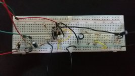
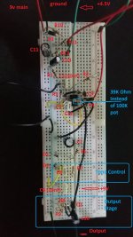
Can you take a couple of photos of your breadboard and post them? Perhaps that will help us find the problem(s).
-Gnobuddy
Okay, the pot is working, and wired correctly. Good!
I removed the pots for distortion, tone and volume. I connected the output directly to C10, I connected R7 to D1,D2 and I connected a 39k resistor between pin 2 and pin 6. The only reason I did this is to be easier remove/replace components.
Is the DMM set to measure DC volts, or AC volts?
DC.
If the source of the problems doesn't click soon, then the best thing to do is to pull everything off the breadboard, and start from scratch, with a much simpler circuit, adding components one by one as you go.
That's what I did before posting here. I started with Just the power supply and Output stage. It worked. Then added Tone control. Still working. Added C7 R6 and the 2 diodes. Still working. Added the rest of the circuit and total mayhem occured 😛.
If you have another type of op-amp handy - one that doesn't need extra capacitors to stabilise it - that might also be a worthwhile switch, at least temporarily.
I have an lm386 but I dont think that I can replace the lm308 with lm386.
That reminds me: you should have a 0.1uF ceramic or film capacitor wired directly across the op-amp power pins (4 & 7), as close as possible to the chip. It's C12 in the schematic, but it should be physically as close as posible to the op-amp power pins, not far away on the breadboard. Do you have this cap in place?
It was away but transfered it near the chip.
Can you take a couple of photos of your breadboard and post them? Perhaps that will help us find the problem(s).
Yes, I will.
Picture one is the top view of the breadboard and picture 2 is the same picture with the indication of each component.
Attachments
And now we're lost in the fog again. The distortion pot was the only thing I knew you had wired correctly, and now you've removed it. 🙁I removed the pots for distortion, tone and volume.
This is not consistent with your report of 0.07 volts on ground, and slowly falling voltage in places where there are no caps.
This was actually useful information, unfortunately you've changed everything since then, so it's no longer useful. 🙁...Just the power supply and Output stage. It worked. Then added Tone control. Still working. Added C7 R6 and the 2 diodes. Still working. Added the rest of the circuit and total mayhem occured 😛.
When you build a circuit in steps, as you did, and a problem suddenly develops, you know that the problem was in the last stage you built. At that point, you should not remove or change anything else - ONLY the last stage you built, as that's the source of the fault.
From your description, you only had problems when you added the op-amp stage. Unfortunately you've changed all the formerly working parts of the circuit since then, so now we don't know if anything is working.
It's time to start over, from scratch, and follow a logical progression this time - i.e., don't rip apart what's working, only what's not working.
You are correct. The LM386 is not an op-amp, but an audio power amplifier chip. An entirely different thing.I have an lm386 but I dont think that I can replace the lm308 with lm386.
I can't see the notch in the IC in your photos, so let's start at the very beginning. Have you positively identified which pin is #1? There is often confusion between the top view of the IC, and the bottom view.
-Gnobuddy
This was actually useful information, unfortunately you've changed everything since then, so it's no longer useful. 🙁
Circuit still works if I bypass the op-amp. If I connect the input directly to C7 positive pin I have a clear output.
It's time to start over, from scratch, and follow a logical progression this time - i.e., don't rip apart what's working, only what's not working.
So I am removing everything that is between input and C7 positive pin. And Rebuild.
I can't see the notch in the IC in your photos, so let's start at the very beginning. Have you positively identified which pin is #1? There is often confusion between the top view of the IC, and the bottom view.
https://www.musikding.de/media/image/product/355/md/lm308_1.jpg
I identify pins as this image indicated. So I consider this a top view. In the pictures I send the notch is heading to the left (or to the top in the picture with the component names).
- Home
- Live Sound
- Instruments and Amps
- Proco RAT Clone doesn't work