Hi Northumber, I am going to ask you a step back question.
- Is there a particular reason you want to go with this complementary topology?
They are substantially harder to bias up than the non-complementary version, specially when loading the diff pairs with current mirrors.
If you still want to attempt the topology, the attached picture shows the simplest way to bias up the VAS current. Bias is via R14 and R16. Actually Kokoriantz already suggested to do this in post #10.
Other techniques are substantially more complicated.
Good luck!
Attachments
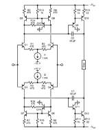
I'm doing it wrong or the current passing through R6 should be 6mA and not 2mA?
The figure is wrong, you have to check each transistors working current and try to find out the problem, like circuit problem or transistors itself have problem
The figure is wrong, you have to check each transistors working current and try to find out the problem, like circuit problem or transistors itself have problem
I simulated the voltages across the points, 0.7V at the base of the transisor and 0.6V across 2.2kohm are correct. Only the voltage across 47ohm (0.1V) should be 0.3V. What does this mean?