I'm having problems in getting one half of a LM319 to work correctly for a over curent detector.
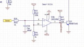
The current sensing resistor consists of 3 x 0.022 Ohm resistors, which should trigger the circuit at a bit more than 16 A. The + input of the Comperator, is connected to a voltage divider 100k/1k to give a 120 mV voltage.
Vcc2 is 12V.
Problem is - input is 0V and + is 120 mV but the output is 10,4 V!!
😕
Doesn't the LM319 work as a window detector this close to ground?
Is it because the differential voltage is two low??
Whe removing R56 the output goes low (makes the diferential voltage 12V).
The Class-d output has not been mounted yet, so this is not the cuase of the problems.
After some experiments I don't find the LM319 too easy to work with 🙁
Anyone familiar with this comparator, that could help??
Attachments
I think the problem is that the common mode input voltage range of the LM319 does not include ground. You need to use the LM339 or one of its dual equivalents.
Yes, like what he said. The LM319 input common mode range does not include ground.
If you look at the data sheet, I haven't found a 'good' one yet, you need something like 1-2V. The internal schematic shows an NPN differential pair with an NPN current mirror driving it's bottom.
That adds up to at least 2 VBE drops or 1.2V if it is going to work.
You might try two resistive dividers from your 12V rail to the inputs to pre-bias them up to 2V. Tie one to ground and the other to your sense resistors.
You'll have to do some sums to set up the proper trip level.
Otherwise there are more modern comparators, as fast or faster, whose input common mode range includes ground.
DNA
The simplest solution: increase Rshunt to twice, and connect to a base of BJT with a pre-bias of 300 mV!
Thanks guys.
This is one more time where simulations does not match real life 🙁
Bad thing is I already made the PCB ... with SMD

Oh well as long as it's fun and as long as I learn something 🙂
..... think a rail to rail op-amp would have don better in this place.
Have also been wondering: I have made the Rsense of 3 x 0.022 Ohm 1W SMD resistors, mostly to avoid wire wound resistors, with their added inductance.
But maybe such a small coil in in the PSU line would actually help dampening ringing and EMI.
SMD in this place is not optimal as SMD components can't handle any real power. I had to pay almost 2$ per SMD resistor!!!!
On the other hand, maybe the small bars Eva is using would be even better .... wonder where these can be obtained!
This is one more time where simulations does not match real life 🙁
Bad thing is I already made the PCB ... with SMD
Oh well as long as it's fun and as long as I learn something 🙂
..... think a rail to rail op-amp would have don better in this place.
Have also been wondering: I have made the Rsense of 3 x 0.022 Ohm 1W SMD resistors, mostly to avoid wire wound resistors, with their added inductance.
But maybe such a small coil in in the PSU line would actually help dampening ringing and EMI.
SMD in this place is not optimal as SMD components can't handle any real power. I had to pay almost 2$ per SMD resistor!!!!
On the other hand, maybe the small bars Eva is using would be even better .... wonder where these can be obtained!
Baldin said:Thanks guys.
This is one more time where simulations does not match real life 🙁
Bad thing is I already made the PCB ... with SMD
Oh well as long as it's fun and as long as I learn something 🙂
..... think a rail to rail op-amp would have don better in this place.
Have also been wondering: I have made the Rsense of 3 x 0.022 Ohm 1W SMD resistors, mostly to avoid wire wound resistors, with their added inductance.
But maybe such a small coil in in the PSU line would actually help dampening ringing and EMI.
SMD in this place is not optimal as SMD components can't handle any real power. I had to pay almost 2$ per SMD resistor!!!!
On the other hand, maybe the small bars Eva is using would be even better .... wonder where these can be obtained!
They are called OAR-3 (for 3W versions) and are obtainable from Farnell, RS etc. The problem is the immense cost of obtaining them, but if you decide on getting some, I might be interested in 4 pcs of 40-50mOhm.
Pafi:
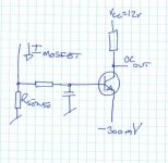
Not sure I get your proposal right ..... by pre-bias, do you mean to tie emitter to -300mV?
If Rsense = 0,015 Ohm then a current of say 20 A would give a 293 mV and together with the 30mV would be just enough to trip the output (probably a little higher current would be needed)!
Se picture. That's what you meant?
But then I have to get the -300mV first, and as it's a full bridge I did not intend to use any negative PSU! 🙁
Zilog:
Thanks for the link to RS ...... well as I was using 3 times 1W SMD resistors .... the OAR thing will only cost a third!!
consort_ee_um and Genomerics:
Well now that I look closer, the data sheet actually states that the input range using 0-5V should be between 1 and 3V .... so for 0-12V I probably ned to go up to the 2V you are suggesting.
Genomerics, I'm not totally sure what you mean .... could you draw a small picture?
Attachments
Baldin, aren't there any other comparators that have an input range down to ground that you could just drop in? That'd be the easiest since you already have the boards made.
I looked up the package for the LM319 but it's quite strange that it's not an SOIC8, or is it?
I thought it would be and you could use something like the LM2903, but it looks like you would need to do some extra wiring to get it to work.
I looked up the package for the LM319 but it's quite strange that it's not an SOIC8, or is it?
I thought it would be and you could use something like the LM2903, but it looks like you would need to do some extra wiring to get it to work.
Baldin said:I'm having problems in getting one half of a LM319 to work correctly for a over curent detector.
The current sensing resistor consists of 3 x 0.022 Ohm resistors, which should trigger the circuit at a bit more than 16 A. The + input of the Comperator, is connected to a voltage divider 100k/1k to give a 120 mV voltage.
Vcc2 is 12V.
Problem is - input is 0V and + is 120 mV but the output is 10,4 V!!
😕
Doesn't the LM319 work as a window detector this close to ground?
Is it because the differential voltage is two low??
Whe removing R56 the output goes low (makes the diferential voltage 12V).
The Class-d output has not been mounted yet, so this is not the cuase of the problems.
After some experiments I don't find the LM319 too easy to work with 🙁
Anyone familiar with this comparator, that could help??
Baldin,
try to do a level shift.
Heinz!
Attachments

Baldin!
BTW:
I see reverse connection on your pic!
On pin7? Connected to Q13?
BTW:
The + input of the Comperator, is connected to a voltage divider
I see reverse connection on your pic!
the output is 10,4 V
On pin7? Connected to Q13?
Bit late in the day..... What Powerbecker/Heinz drew....
Same idea, mine is more stupid though...
DNA
Same idea, mine is more stupid though...
DNA

powerbecker:
Thanks .... that cleared it up 🙂
Think I'll try that first, as it will be easiest to implemtent on the current PCB 😉
Pafi
The circuit is "right" ... the divider is conected to - and not + as I wrote!
Yes the output is high = 10,4V on pin 7 which is connected to the base of the following Q13.
Otherwise like your approach .... will try that on the next D thing .... didn't think of the pre-bias, and thought I couldn't trip a BJT directly from the current sensing resistor.😉
The circuit is "right" ... the divider is conected to - and not + as I wrote!
OK, but then what is the problem? When "+" is positiver then "-", then high output is normal...
Yes the output is high = 10,4V on pin 7 which is connected to the base of the following Q13.
...except in this case. 10,4V on a good B-E diode is impossible.
The 10,4V is measured with Q13 dismounted.
Don't know where the basis resistor for Q13 went! (as the LM319 is an open collector output, Q13 will be biased through R57 (2k2) and will still work, though it was not intended to be designed this way..... think I will increase R57 to 10k to lower the basis current in Q13!!
Problem is that when plus is tied to ground (or no current is running in the sense resistor), then minus is higher (set by the divider), but the output is high (10,4 V)
Now that I'm digging a bit, I have found the simulations .... and find that these are using a TL072 as comparator .... and that it includes a bias resistor for Q13 ...... think I have been a little to fast here
The only reason I'm using the LM319 in this place is because I had one half free, as the other half is used in the oscillator
Don't know where the basis resistor for Q13 went! (as the LM319 is an open collector output, Q13 will be biased through R57 (2k2) and will still work, though it was not intended to be designed this way..... think I will increase R57 to 10k to lower the basis current in Q13!!
Problem is that when plus is tied to ground (or no current is running in the sense resistor), then minus is higher (set by the divider), but the output is high (10,4 V)
Now that I'm digging a bit, I have found the simulations .... and find that these are using a TL072 as comparator .... and that it includes a bias resistor for Q13
...... think I have been a little to fast hereThe only reason I'm using the LM319 in this place is because I had one half free, as the other half is used in the oscillator
Problem is that when plus is tied to ground (or no current is running in the sense resistor), then minus is higher (set by the divider), but the output is high (10,4 V)
Oops, you are right.
- Status
- Not open for further replies.
- Home
- Amplifiers
- Class D
- Problems with LM319