I was listening to crystal clear music only to have it interupted by some nasty sounding static and noise. I traced this down to a Mica? small value cap on pin 3 of the output tube socket. I had a small value cap rated at 600volts so I replaced it to see what happens. It was clean sounding again.
Question :
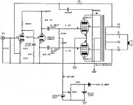
Anyone know the value of this cap, I haven't seen one of these in over 40yrs. It looks like it has been hot and I can't read the paint dot scheme that would probably tell me what the heck it was. The schematic looks like it shows 100UF or is it PF?
Also there is a 5K resistor shown in the feedback on the schematic and their is a 562 ohm in the amp.
Any help would be appreciated.
Joe
Question :
Anyone know the value of this cap, I haven't seen one of these in over 40yrs. It looks like it has been hot and I can't read the paint dot scheme that would probably tell me what the heck it was. The schematic looks like it shows 100UF or is it PF?
Also there is a 5K resistor shown in the feedback on the schematic and their is a 562 ohm in the amp.
Any help would be appreciated.
Joe
Joe,
If you can't post the schematic can you tell us what the output tube is? It would then be possible to determine the function of the cap and possible values from the pin connections...
(i.e. if pin three is the cathode, 100uf would be ok as a cathode bypass, but if pin three was the anode, then with 100uf you wouldn't be hearing anything!)
Hi,
It connects from pin 3 (the anode of a 8417) to the NFB loop and EC8010 is correct 100pF is the value.
If that 562R is correct than that's a hell of a lot of FB.
Cheers,")
(i.e. if pin three is the cathode, 100uf would be ok as a cathode bypass,
It connects from pin 3 (the anode of a 8417) to the NFB loop and EC8010 is correct 100pF is the value.
Also there is a 5K resistor shown in the feedback on the schematic and their is a 562 ohm in the amp.
If that 562R is correct than that's a hell of a lot of FB.
Cheers,
Frank
Yup its a 562ohm 1% nasty looking black resistor about the thickness of my little finger and I would assume its a 3 or 5 watt job. The resistor is going to be replaced per the 8417 conversion guide that was on the board a while back. I think I will use somewhere around 270 ohm.
I wasn't able to purchase a mica capacitor but did snag a 100pf/600volt film to replace the original.
What are the correct values of the resistors on the cathode of the 12AX7 to ground? I think I can see a 820 but the other value is blurred on my schematic.
Any suggestions for hot rodding this garage amp?
Per Mike at Quicksilver the impedance of the output transformer is Quote "Closer to 3900 ohms" not 4200ohms.
The schematic I posted looks much better than what printed off for me.
Joe
Attachments
QS.
Hi Joe,
Ouch,even more FB?..Beyond me really, why? What board you mean?
Should be fine.
820R on top and 220R at the bottom.
Depends on what you want to achieve.
He should know, the ones I saw had 4K2 written on the OPTs but who am I, right?
Cheers,
Hi Joe,
Yup its a 562ohm 1% nasty looking black resistor about the thickness of my little finger and I would assume its a 3 or 5 watt job. The resistor is going to be replaced per the 8417 conversion guide that was on the board a while back. I think I will use somewhere around 270 ohm.
Ouch,even more FB?..Beyond me really, why? What board you mean?
I wasn't able to purchase a mica capacitor but did snag a 100pf/600volt film to replace the original.
Should be fine.
What are the correct values of the resistors on the cathode of the 12AX7 to ground? I think I can see a 820 but the other value is blurred on my schematic.
820R on top and 220R at the bottom.
Any suggestions for hot rodding this garage amp?
Depends on what you want to achieve.
Per Mike at Quicksilver the impedance of the output transformer is Quote "Closer to 3900 ohms" not 4200ohms.
He should know, the ones I saw had 4K2 written on the OPTs but who am I, right?
Cheers,
5k or 562 Ohms...
If the feedback resistor it was 562 Ohms the voltage gain of your amp wil be 3,5X ...so with a 1Volt input you only get 3.5 Volt at the output...
So definitively must be 5k ...for the voltage gain to be 24 X..
It seems to be 220 Ohms
Regards
Also there is a 5K resistor shown in the feedback on the schematic and their is a 562 ohm in the amp
If the feedback resistor it was 562 Ohms the voltage gain of your amp wil be 3,5X ...so with a 1Volt input you only get 3.5 Volt at the output...
So definitively must be 5k ...for the voltage gain to be 24 X..
What are the correct values of the resistors on the cathode of the 12AX7 to ground? I think I can see a 820 but the other value is blurred on my schematic
It seems to be 220 Ohms
Regards
RE:Speedy Gonzales...
Hi,
Wait till Summer...I am still hibernating.
You're not too bad either in the speed department...
Um abracao, (wrong keyboard settings to spell it correctly)
Hi,
Speedy Gonzales...
Wait till Summer...I am still hibernating.
You're not too bad either in the speed department...
Um abracao,
(wrong keyboard settings to spell it correctly)SPEEDY.
Hi,
That would change matters only for the worse...if you believe too much NFB is a bad thing.
Taking the 8R path is only increasing FB even more since the series resistance from 8R to 16R isn't there anymore.
Cheers,
Hi,
The feedback resistor is on the 8ohm leg of the transformer.
That would change matters only for the worse...if you believe too much NFB is a bad thing.
Taking the 8R path is only increasing FB even more since the series resistance from 8R to 16R isn't there anymore.
Cheers,
Bad news!
Actualy is the oposite...the feedback will be decreased...
The output transformer as more voltage gain in the 16 Ohms tap so the open loop voltage gain is greater..
When you change for the 8 Ohm tap the open loop voltage gain is reduced...so the feedback will be decreased...
Um abração!
Taking the 8R path is only increasing FB even more since the series resistance from 8R to 16R isn't there anymore.
Actualy is the oposite...the feedback will be decreased...
The output transformer as more voltage gain in the 16 Ohms tap so the open loop voltage gain is greater..
When you change for the 8 Ohm tap the open loop voltage gain is reduced...so the feedback will be decreased...
Um abração!
http://www.triodeel.com/8417.htm
The article (8417.htm) explains how to convert a 8417 to use 6550's. Http://WWW.triodeel.com/8417.htm
It makes mention to the 562ohm resistor in the feedback loop. If the 562 ohm resistor was the original part what changes would their have been to the 820 and 220 cathode resistors on the 12AX7?
Joe
The article (8417.htm) explains how to convert a 8417 to use 6550's. Http://WWW.triodeel.com/8417.htm
It makes mention to the 562ohm resistor in the feedback loop. If the 562 ohm resistor was the original part what changes would their have been to the 820 and 220 cathode resistors on the 12AX7?
Joe
Late night talking
Yes but for me problem is elsewhere...as you say...summer is comming...Frank is hibernatin...
Um abraço
PS. In your part of bellgium what is the oficial language?
it's getting late
Yes but for me problem is elsewhere...as you say...summer is comming...Frank is hibernatin...
Wait till Summer...I am still hibernatin
Um abraço
PS. In your part of bellgium what is the oficial language?
QS.
Hi,
Joe, I can only assume that's a typo.
The original FB resistor was 5K in all units I have seen, a 1W Dale if memory serves.
So nothing changes at the first tube one way or the other.
Ciao,
Hi,
It makes mention to the 562ohm resistor in the feedback loop.
Joe, I can only assume that's a typo.
The original FB resistor was 5K in all units I have seen, a 1W Dale if memory serves.
So nothing changes at the first tube one way or the other.
Ciao,
HIBERNATION...HIGHLY RECOMMENDED.
Hi,
Officially, that would be Flemish....the city being on the bordeline of three provinces we have about a fifty-fifty population here.
Half Flemish, half French speaking (I wouldn't call it French though, it's more like a dialect).
Ciao,
Hi,
PS. In your part of bellgium what is the oficial language?
Officially, that would be Flemish....the city being on the bordeline of three provinces we have about a fifty-fifty population here.
Half Flemish, half French speaking (I wouldn't call it French though, it's more like a dialect).
Ciao,
Thanks Frank
You know of the condition of this pair of 8417's that I have. I'm sure they have had their share of little hands in them. If you say its a 5K I will change them to 5K resistors. This does answer my questions as to why the 220ohm resistors had been changed to a different value.
Frank
I have set number three of mono block Quicksilvers headed my way. These are virgins and have extra 8417 tubes. I guess I'm stuck on them.
Joe
OH DEAR...
Hi Joe,
Man, you really have the tube bug.
Well, you know where to find us.
Cheers,
Hi Joe,
I have set number three of mono block Quicksilvers headed my way. These are virgins and have extra 8417 tubes. I guess I'm stuck on them.
Man, you really have the tube bug.
Well, you know where to find us.
Cheers,
- Status
- This old topic is closed. If you want to reopen this topic, contact a moderator using the "Report Post" button.
- Home
- Amplifiers
- Tubes / Valves
- Problem with Quicksilver amp