To be honest if you have the new parts, you may as well just replace them all. There's no need to check the electrolytic capacitors - they WILL be due for replacement due to the age of the unit, and the high temperature.
For testing transistors, you really need a meter with a proper diode check function.
For testing transistors, you really need a meter with a proper diode check function.
I have a tester like this one:To be honest if you have the new parts, you may as well just replace them all. There's no need to check the electrolytic capacitors - they WILL be due for replacement due to the age of the unit, and the high temperature.
For testing transistors, you really need a meter with a proper diode check function.
Multimetro digitale GBC KDM-110 - Attrezzature di lavoro In vendita a Torino
It has the funtion for test the transistor I think (Is it the part in the bottom right where is written NPN and PNP)... Am I right?
The resistor seems to be fine... I've tested them with the tester.
I will replace all the caps with new caps with 105°C so they should "survive" more.
I will replace the transistor in the TO3 format (MJ15003 and MJ15004) and their driver transistor BD135 and BD136 with BD139 and BD140, must I to control the other transistors?
2) I've choosen to replace the caps in the signal with some Mundorf M-Cap 1uF 400V (I've used it for replace some output caps with wonderfull results), is it a good choise?
3) I've readen that some people replaced the C15 and C16 caps (in the signal) with some silver mica caps, is it a good choice?
P.S. sorry for my awful english but I think you can undestand and for all this many question.
I realized something looking good of the rectifying diodes in the main power supply: there are 4 diodes... two of them are 1N5401 - 100V 3A, one of them is 5404 - 400V 3A (this seems really broken) and the last I can't write anything. 🙁
Now, from the main power supply schematic here:
Musical Fidelity A1 - Technical
I read that the diodes must be BY255 that are qualified for 1300V 3A... Could this be why the diodes are broken?
Can you conferm that the right diodes are BY255 as the schematic, can you?
Now, from the main power supply schematic here:
Musical Fidelity A1 - Technical
I read that the diodes must be BY255 that are qualified for 1300V 3A... Could this be why the diodes are broken?
Can you conferm that the right diodes are BY255 as the schematic, can you?
The diodes are rectifying ~18 volts AC, a high voltage rating is not necessary in the least.
Please do beware that the A1 is not short circuit proof and you will blow the output stage if you should happen to do so, so be very careful when testing.
Please do beware that the A1 is not short circuit proof and you will blow the output stage if you should happen to do so, so be very careful when testing.
I can't understand so good: you are saying me that the diodes must rectify 18 V AC so a higher voltage is not necessary, so what diode do you reccomend me?The diodes are rectifying ~18 volts AC, a high voltage rating is not necessary in the least.
Please do beware that the A1 is not short circuit proof and you will blow the output stage if you should happen to do so, so be very careful when testing.
What is the output stage and what part must I test, please?
The output stage = the MJ15003, MJ15004,BD139 & BD140 replacement parts. From what I remember the A1 doesn't have any protection built in, so if you short circuit the output the MJ transistors will have to deliver more current then they are capable of and they will explode.
As the A1 is class A there is very little that you can actually do to test it besides just turning it on. But if you were going to connect some cheap loudspeakers to it to test it, just be careful not to short circuit the outputs.
The 1N540X series is a series of diodes that are rated for up to 3A use. They come in a variety of different voltages.
http://www.diodes.com/datasheets/ds28007.pdf
Any of the series will do. I would choose the 1N5401 as the minimum though just to be on the safe side. The fact their are different diodes in your A1 isn't a surprise, Musical Fidelity probably purchased the diode from the series that was the least expensive when bought in bulk at the time. In other words, one month they may have purchased 1000 1N5401s then the next month they purchased 1000 1N5404s as they were cheaper. There's nothing wrong with that, both parts are suitable.
Thanks a lot!The output stage = the MJ15003, MJ15004,BD139 & BD140 replacement parts. From what I remember the A1 doesn't have any protection built in, so if you short circuit the output the MJ transistors will have to deliver more current then they are capable of and they will explode.
As the A1 is class A there is very little that you can actually do to test it besides just turning it on. But if you were going to connect some cheap loudspeakers to it to test it, just be careful not to short circuit the outputs.
The 1N540X series is a series of diodes that are rated for up to 3A use. They come in a variety of different voltages.
http://www.diodes.com/datasheets/ds28007.pdf
Any of the series will do. I would choose the 1N5401 as the minimum though just to be on the safe side. The fact their are different diodes in your A1 isn't a surprise, Musical Fidelity probably purchased the diode from the series that was the least expensive when bought in bulk at the time. In other words, one month they may have purchased 1000 1N5401s then the next month they purchased 1000 1N5404s as they were cheaper. There's nothing wrong with that, both parts are suitable.
I've disassembled completely my A1-X because was broken (if you read the first page of this thread you can understand); now I'm waiting some new components:
- MJ15003 and MJ15004 for A1N and A1P;
- BD139/BD140 for BD135/BD136;
- all the caps with some panasonic FC 105 °C (the supply caps too);
- some caps in the signal with MKP Mundorf M-Cap;
Have I to replace the R1/R2 and R30/R31 resistor (0,47 ohm and 0,22 ohm 2W)??? Because with my tester I can't measure them.
I do have an A1 myself so I am reasonably familiar with it. Although the insides are now gutted to be replaced with something else at a later date.
Those resistors are of extremely low value so when read with a multimeter they should basically measure as a short circuit. If you're measuring them and getting nothing, as in open circuit, like the resistor isn't there, then they are fried and will need replacing. It isn't a surprise that those resistors are destroyed.
Those resistors are of extremely low value so when read with a multimeter they should basically measure as a short circuit. If you're measuring them and getting nothing, as in open circuit, like the resistor isn't there, then they are fried and will need replacing. It isn't a surprise that those resistors are destroyed.
My opinion is to replaced:
1) all the electrolytics at pre- and final stage with 105°C (Panasonic FC or BC caps are very fine)
2) all the psu electrolytics with 10000/35V - 15000/35V. Attention to the high of capacitors - I think so that the max is 35-40mm.
3) the four PSU diodes with BY255 (factory setup) or Vishay BYT56M-TR
4) the output devices are pairs 2N3055/MJ2955 from factory. Replaced them with MJ15003G/15004G pairs. They are more highly rated and reliable.
5) When you changed the output devices, you must very carefull. Look the initial fix and doing the same.
6) The collector resistors R30,31 must be a rated 3-5W and not 2W, 5W is better. If the temperature of the upper case are very hot (>65°C), change the R30,31 with 0,33 Ohm (you will have a smaller quiescent current).
7) With no input and no output, put your multimeter to the speaker outputs (Vdc rate) you must had ≤ 50mVdc.
1) All the electrolytics will be Panasonic 105°C (only 4 caps in the signal will be MKP Mundorf M-Cap);My opinion is to replaced:
1) all the electrolytics at pre- and final stage with 105°C (Panasonic FC or BC caps are very fine)
2) all the psu electrolytics with 10000/35V - 15000/35V. Attention to the high of capacitors - I think so that the max is 35-40mm.
3) the four PSU diodes with BY255 (factory setup) or Vishay BYT56M-TR
4) the output devices are pairs 2N3055/MJ2955 from factory. Replaced them with MJ15003G/15004G pairs. They are more highly rated and reliable.
5) When you changed the output devices, you must very carefull. Look the initial fix and doing the same.
6) The collector resistors R30,31 must be a rated 3-5W and not 2W, 5W is better. If the temperature of the upper case are very hot (>65°C), change the R30,31 with 0,33 Ohm (you will have a smaller quiescent current).
7) With no input and no output, put your multimeter to the speaker outputs (Vdc rate) you must had ≤ 50mVdc.
2) the psu electrolytics will be Panasonic TS-HA 10000uF 35V;
3) I've bought some 1N5401 (100V 3A) for psu diodes... are you sure that I need thode BY255, I say this because my amp is a A1-X that should use 1N5401 in the original schematics;
4) I'll use MJ15003 and MJ15004;
5) I will carefully;
6) I've bought those resistor 2W... are you sure that must be 3/5W???
7) I'll try it before connect the wires;
The A1 and the A1-Anniversary had BY255 diodes. Any diodes with this characteristics are be fine.
At the schematics of Mark Hennessey, the rating of collector resistors are 2W. At the A1 Anniversary, these are 5 W ratings. You can use 2W collector resistors, but don't put them close to pcb. Leave ≈ 1 cm distance (high temprature).
Good luck!
At the schematics of Mark Hennessey, the rating of collector resistors are 2W. At the A1 Anniversary, these are 5 W ratings. You can use 2W collector resistors, but don't put them close to pcb. Leave ≈ 1 cm distance (high temprature).
Good luck!
Ok, BY255 are coming.
A1 anniversary is the same amp of A1-X? 😕
For the resistances I'm uncertain; I still have a chance to fill the order with MOX resistors 5W, if you think they're really better, tell me that I'll fill that order of 5W.
Thanks.
A1 anniversary is the same amp of A1-X? 😕
For the resistances I'm uncertain; I still have a chance to fill the order with MOX resistors 5W, if you think they're really better, tell me that I'll fill that order of 5W.
Thanks.
My english is not very well to explain with more detail, about collector resistors. More watt is better with temperature coefficient (if I remember the term right).
Look the characteristics of these resistors vs temperature rise. The less heat resistor the better.
The A1-Anniversary was a collective version of A1 with 250 items production only. It had better PSU, some quality capacitors and probably match outpute transistors whith the stamp of "A1 10th Anniversary".
This amplifier I've yet and I hear it only as a final amp.
Probably I' ll returned to factory setup, like a vintage amp.
This photo is from PSU section of A1 10th Anniversary (factory setup)
An externally hosted image should be here but it was not working when we last tested it.
Last edited:
Thanks for all... I can understand your english good.My english is not very well to explain with more detail, about collector resistors. More watt is better with temperature coefficient (if I remember the term right).
Look the characteristics of these resistors vs temperature rise. The less heat resistor the better.
The A1-Anniversary was a collective version of A1 with 250 items production only. It had better PSU, some quality capacitors and probably match outpute transistors whith the stamp of "A1 10th Anniversary".
This amplifier I've yet and I hear it only as a final amp.
Probably I' ll returned to factory setup, like a vintage amp.
This photo is from PSU section of A1 10th Anniversary (factory setup)
Say hello to Greece, a country I have visited four times and I learned to love... 🙂
The transistors MJ15003 and MJ15004 are arrived today but I have a problem.
In the old transistors the writing and A1N A1P seem to be opposed to the MJ15003 and MJ15004 written, do you know if it is so or not?
In the old transistors the writing and A1N A1P seem to be opposed to the MJ15003 and MJ15004 written, do you know if it is so or not?
Don't worry!
The A1N are NPN Transistor like MJ15003
The A1P are PNP Transistor like MJ15004
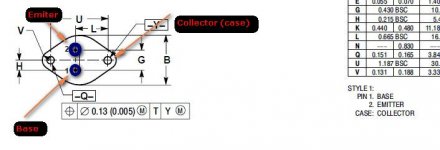
Both of them has the same schematic, with the same position of Base (B), Collector (C), Emitter (E). Look at the bottom of transistor, don't look the upper letters.
Look at attachment schema and marks the signs (B,C,E) to your transistors. Then look at the A1N & A1P where are the cables and doing the same.

Are you understood?
(Greetings from Greece...)
The A1N are NPN Transistor like MJ15003
The A1P are PNP Transistor like MJ15004
Both of them has the same schematic, with the same position of Base (B), Collector (C), Emitter (E). Look at the bottom of transistor, don't look the upper letters.
Look at attachment schema and marks the signs (B,C,E) to your transistors. Then look at the A1N & A1P where are the cables and doing the same.
Are you understood?
(Greetings from Greece...)
Attachments

I have found four diodes 1N5406 (600V 3A) and four BY255 (1300V 3A)... what is the better choice???
- Status
- Not open for further replies.
- Home
- Amplifiers
- Solid State
- Problem with my Musical Fidelity A1-X