Yes, the IC appears as though it will contain most of the circuitry.
Does it have a type number on it ?
The letters and numbers are laid out very similar to this picture of another chip I found online after searching "NEC driver IC", though I'm unsure weather the font for "NEC" is exactly the same, so weather it references that company or not I'm not sure.

The type number will be in amongst the digits you see. It could be a uPC1270H. Does it have the same umber of legs ?
Semiconductor: UPC1270 (UPC 1270) - AUDIO DRIVER 12P...
Semiconductor: UPC1270 (UPC 1270) - AUDIO DRIVER 12P...
Attachments
The type number will be in amongst the digits you see. It could be a uPC1270H. Does it have the same umber of legs ?
Semiconductor: UPC1270 (UPC 1270) - AUDIO DRIVER 12P...
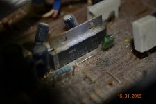
With a head torch and a precariously placed camera, I managed to get a picture of the chip. 🙂
The number isn't the one you linked, but as you can see it's similar.
I think the one you linked was a newer chip.
As you can see, it the font for the logo is different, the chip in my amp being the font the company used to use.
It has 12 legs as far as I can see, so the same, yes.
to get the picture right I very gently pressed the chip forward, and now when I've tested the amp again with my speakers, all channels appear to be working longer than they usually do.
The amp sometimes produces a clean signal, as I explained, but then reverts back to the crackling after five minuets or so, or if the amp is turned on and off, it depends.
This time though, it's been okay for about 15 minuets, which is odd...
Attachments
Last edited:
The type number will be in amongst the digits you see. It could be a uPC1270H. Does it have the same umber of legs ?
Semiconductor: UPC1270 (UPC 1270) - AUDIO DRIVER 12P...
Only just noticed the PDF, I'll have a read, thank you.
Well a quick comparison of data sheets show them to be similar, very similar. Donberg list the 1225.
Before you jump in and start thinking about replacing this, you should first check for all other possibilities such as poor soldering on any of the pins (and on any of the other circuitry)
If the amp is OK at the moment then it could be because the lid is off and its running cooler. Try a hair drier on the area around the chip and see if the fault appears. Also give the board a clean with a vacuum and soft brush 😉
Attachments
Well a quick comparison of data sheets show them to be similar, very similar. Donberg list the 1225.
Before you jump in and start thinking about replacing this, you should first check for all other possibilities such as poor soldering on any of the pins (and on any of the other circuitry)
If the amp is OK at the moment then it could be because the lid is off and its running cooler. Try a hair drier on the area around the chip and see if the fault appears. Also give the board a clean with a vacuum and soft brush 😉
Interesting.
And yeah, I'm not sure how to actually check the soldering is the thing.
It seems there's quite a but to take apart which I'm a bit worried about, not being very savvy with circuitry other than with the basics.
Presumably once unscrewed, you just flip the board over and everything will be visible?
Also, the Driver IC chips we were discussing - there are two.
Does this mean I'd be replacing both if that what I end up doing?
And agreed, haha. I was a little worried to start vacuuming the board for fear I might suck something up by mistake if it was loose! 🙂
Thanks for your help.
There is one IC per channel (left and right), and yes, you have to dismantle it to get at the underside of the board.
I'm re-reading your first post. When you said the problem had spread from 'one channel to all of them', do you mean channel as in just the left and right output, or channel as in all the inputs ?
You would be very unlucky indeed for both IC's to fail and to give the same type of fault in each channel (the left and right). So if the crackling is on both left and right then we need to look elsewhere first.
The two priorities are to clean that board up so we can see it all better 😉 and for you to give it all a good visual inspection underneath. Looking for dries is the first thing to do.
Are you sure the crackling doesn't respond to physical prodding and poking. Have you prodded the front panel circuit board ?
There is one IC per channel (left and right), and yes, you have to dismantle it to get at the underside of the board.
I'm re-reading your first post. When you said the problem had spread from 'one channel to all of them', do you mean channel as in just the left and right output, or channel as in all the inputs ?
You would be very unlucky indeed for both IC's to fail and to give the same type of fault in each channel (the left and right). So if the crackling is on both left and right then we need to look elsewhere first.
The two priorities are to clean that board up so we can see it all better 😉 and for you to give it all a good visual inspection underneath. Looking for dries is the first thing to do.
Are you sure the crackling doesn't respond to physical prodding and poking. Have you prodded the front panel circuit board ?
Very important questions!
Furthermore I don't see any evidence the problem is not about the speakers. Check that first! (By changing amp, or changing speaker (or simply swapping if they sound significantly different), or measuring/recording/uploading output voltage, or damp speaker membrane by hand and see if it affects the crackling, etc...)
There is one IC per channel (left and right), and yes, you have to dismantle it to get at the underside of the board.
Right, I see.
I'm re-reading your first post. When you said the problem had spread from 'one channel to all of them', do you mean channel as in just the left and right output, or channel as in all the inputs ?
My apologies, that is my inexperience showing through - I thought Channel referred to one input, so I did in fact mean, all the inputs.
You would be very unlucky indeed for both IC's to fail and to give the same type of fault in each channel (the left and right). So if the crackling is on both left and right then we need to look elsewhere first.
The two priorities are to clean that board up so we can see it all better 😉 and for you to give it all a good visual inspection underneath. Looking for dries is the first thing to do.
Indeed.
Well I've given the board a good clean with a brush and vacuum as you suggested, and have gone where they can't go with a q-tip, so it's looking better now.
I'll open up and see if I can spot anything on there with the soldering.
Are you sure the crackling doesn't respond to physical prodding and poking. Have you prodded the front panel circuit board ?
That's an interesting question, because as I said earlier, when was moving around the driver IC to take that picture and plugged everything back in, the amp has been working fine ever since.
I ran it for a good 20 minuets and experienced no crackling.
After cleaning it I plugged it in again just now, and it still works fine.
I tested speakers on all four channels and everything seems to be working.
As you said, this could have been because the amp was running cooler with the lid off, but it hasn't had the lid on for about a week now, and within that time it's crackled the same as it always had, so I'm not sure.
I did prod around with the front panel to see if anything was broken.
Very important questions!
Furthermore I don't see any evidence the problem is not about the speakers. Check that first! (By changing amp, or changing speaker (or simply swapping if they sound significantly different), or measuring/recording/uploading output voltage, or damp speaker membrane by hand and see if it affects the crackling, etc...)
Yes I should've mentioned this in the first place, sorry.
It's definitely not the speakers.
I've tried both pairs of speakers I own - both my Hi-Fi reference speakers and audio monitors - and both have the exact same problem.
I've swapped the speakers around and whatever was wrong coming through on the right speaker would then come through on the left, so It's definitely the amp that's the issue.
Thanks for the reply.
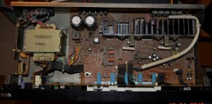
You also do need to check the joints of the transistors. That heatsink looks very marginal, causing the transistors to heat up significantly. Over the years this thermal cycling - as the amp heats up and then cools down again - places enormous stress on the joints. I wouldn't be surprised to find the entire board needing a resoldering operation. Sometimes just that alone can fix a lot of issues.
Also do check/reflow all the joints connecting the thermal compensation PCB to the main PCB, as well as the devices connected to the PCB itself. This is the small PCB between the black an green transistors on the main sink. While you get this done, do replace the trimmers on that PCB, they may have lost contact. They usually do, and that type is notorious for failing after a decade. Not too shabby for what they cost though.
It does not appear to have any sort of speaker protection, so I wouldn't connect a good pair to it while powering up after any changes. Finally, recheck the joints connecting all external connectors to the board - RCA, binding posts and all switches. If the crackling gets worse with changes in the volume control position, it may be a problem with a worn track on the control potentiometer and you may need to change it out. Finding it will be quite the task though, but if can post a pic from the front, maybe there will be a few responses.
20 years is a long time, but I've seen older units survive. The sound quality usually goes to pot, and problems like this are quite common. However they're mostly fixable, so keep at it.
You also do need to check the joints of the transistors. That heatsink looks very marginal, causing the transistors to heat up significantly. Over the years this thermal cycling - as the amp heats up and then cools down again - places enormous stress on the joints. I wouldn't be surprised to find the entire board needing a resoldering operation. Sometimes just that alone can fix a lot of issues.
Also do check/reflow all the joints connecting the thermal compensation PCB to the main PCB, as well as the devices connected to the PCB itself. This is the small PCB between the black an green transistors on the main sink. While you get this done, do replace the trimmers on that PCB, they may have lost contact. They usually do, and that type is notorious for failing after a decade. Not too shabby for what they cost though.
It does not appear to have any sort of speaker protection, so I wouldn't connect a good pair to it while powering up after any changes. Finally, recheck the joints connecting all external connectors to the board - RCA, binding posts and all switches. If the crackling gets worse with changes in the volume control position, it may be a problem with a worn track on the control potentiometer and you may need to change it out. Finding it will be quite the task though, but if can post a pic from the front, maybe there will be a few responses.
20 years is a long time, but I've seen older units survive. The sound quality usually goes to pot, and problems like this are quite common. However they're mostly fixable, so keep at it.
There is one IC per channel (left and right), and yes, you have to dismantle it to get at the underside of the board.
I'm re-reading your first post. When you said the problem had spread from 'one channel to all of them', do you mean channel as in just the left and right output, or channel as in all the inputs ?
You would be very unlucky indeed for both IC's to fail and to give the same type of fault in each channel (the left and right). So if the crackling is on both left and right then we need to look elsewhere first.
The two priorities are to clean that board up so we can see it all better 😉 and for you to give it all a good visual inspection underneath. Looking for dries is the first thing to do.
Are you sure the crackling doesn't respond to physical prodding and poking. Have you prodded the front panel circuit board ?
I've dismantled the amplifier amplifier now.
removing the board from the actual casing seemed to be impossible - the power supply was fixed and irremovable to the outer casing, and the outer casing's parts were welded together, so It was a bit cumbersome.
What I have now though is the parts separated from each other at least after removing the screw.
It's enabled me to examine the soldering of all components.
I've attached images explaining my findings.
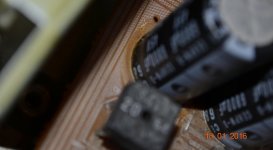
The first thing I noticed was a yellowing underneath the big, black capacitors.
Wasn't sure weather this was normal or not or weather it was a leak, but a quick search online showed a leak to an average cap leak to either be visible from the slits at the top, or most cases to have completely destroyed the PCB underneath creating a hole.
the second thing I saw was some candle wax, that appeared to have seen spilt through the grill on the outside case, onto the PCB and through to the bottom.
It was only on the board, and didn't come into contact with any components, and I got rid of it and wiped the area clean.
Next I started to examine the soldering on the main board, to see if I could spot any examples of drying, and I saw that on a fair few solder points, there was an orange, sticky looking substance around the solder.
In terms of the drying, I have to say I couldn't really tell weather it's dried up or is okay.
Obviously, there are examples online I've seen where it's obvious, but may like the picture you linked, Mooley, weren't so obvious to my untrained eye.
The last thing I found was a leg of a component that broke off when I brushed the board clean - It had clearly been hanging on by a tiny thread for some time and came right off as the brush passed over it.
I didn't even realize until I heard it drop down into the case.
I picked it out and tried to find where it came from but unfortunately I couldn't, so I have the broken piece here next to me.
Sangram - Checked the thermal compensation PCB connections and everything seems to be soldered okay, both on the PCB it's self and the solder connecting it to the main PCB.
Not sure what you mean by trimmers? Did a quick search online but I'm still confused..
Undrstood on the speaker protection issue.
The photo's attached show all of what I explained as well as a full shot of the board.
EDIT: After looking again I've noticed what looks to be cracked/dried solder.
The solder appears to be connecting the 8 inputs on the back of the amp.
Thank you both for the help.

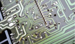
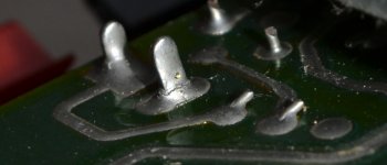
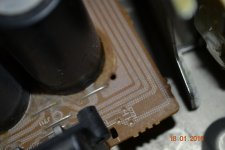
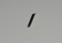
It looks like the IC pins have all cracked off the board/ can clearly see circular cracks in the solder around the pins. I think a full reflow is in order. Not sure what to do about the broken pin, but if you can't see any component with a pin missing (look for it like you would hunt down a broken tooth, it'd be pretty obvious) so it may be random debris.
The capacitors will need replacing/lots of heat damage from the brown colour on the board, likely caused over the years. I can see a bit of electrolyte corrosion on the board just under the cap, but the pic is not in focus so can't tell for sure.
That brown stuff around the components and tracks is essentially flux that was originally around the pads, but melted and flowed around the board because of the heat (at least, that's what the pics indicate). Capacitors that have spent so much time under heat will need replacing.
As for the trimmers, you can see a small slot to insert a flat-tipped screwdriver in the middle of the PCB, through a hole in the board itself. That is the underside of a three-legged trimmer and the board may need to be removed to replace that part.
There is a lot of discoloration around the right-hand side driver IC, likely caused by the big blue resistor. My guess is that it is the supply resistor for both the driver chips, unfortunately can't see the colour code as it's obscured by the signal input wire in the picture. That is what would have caused the crackling in the first place - and the right channel would have been the one to die first, correct? That chip has lost every single solder pad contact.
It looks like the IC pins have all cracked off the board/ can clearly see circular cracks in the solder around the pins. I think a full reflow is in order.
Oh, So it has.
Just got back home from college so and I couldn't look at the uploaded images I'd blown up on the Ipad for some reason.
It's clear now I'm on my desktop PC and can, to the naked eye that wasn't visible.
Perhaps there are more pins that have dried throughout the board.
All I spotted initially was the one by the inputs.
I'll have another look.
Understood.Not sure what to do about the broken pin, but if you can't see any component with a pin missing (look for it like you would hunt down a broken tooth, it'd be pretty obvious) so it may be random debris.
I'll go through and check again.
I'll have another look - the camera wasn't focusing for some reason.The capacitors will need replacing/lots of heat damage from the brown colour on the board, likely caused over the years. I can see a bit of electrolyte corrosion on the board just under the cap, but the pic is not in focus so can't tell for sure.
I see.That brown stuff around the components and tracks is essentially flux that was originally around the pads, but melted and flowed around the board because of the heat (at least, that's what the pics indicate). Capacitors that have spent so much time under heat will need replacing.
You mentioned pads, what are they exactly?
Oh yeah, I see it. Thanks.As for the trimmers, you can see a small slot to insert a flat-tipped screwdriver in the middle of the PCB, through a hole in the board itself. That is the underside of a three-legged trimmer and the board may need to be removed to replace that part.
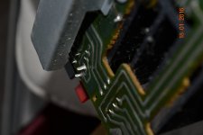
I've linked a picture because I wasn't sure what the signal input wire was, haha!There is a lot of discoloration around the right-hand side driver IC, likely caused by the big blue resistor. My guess is that it is the supply resistor for both the driver chips, unfortunately can't see the colour code as it's obscured by the signal input wire in the picture. That is what would have caused the crackling in the first place - and the right channel would have been the one to die first, correct? That chip has lost every single solder pad contact.
Is it the blue or yellow circled resistor you're referring to? I would presume the wire you're talking about is the big one, so the yellow one?
The right channel was the first to go, indeed.
You're clearly very well informed - I was wondering where is the best place to start to learn about this stuff? I have a very basic understanding of electronics but I need to learn more.
Thanks allot.
Attachments
Yes, a full resolder is in order here. Those IC's look as though they could almost be removed 🙂 I would advice going over all the joints although those obvious ones are almost certainly the cause of the trouble at the moment.
You need to be careful when doing this work because its easy to accidently short something and not notice, or for a blob of solder to fall on the board and go unnoticed.
You need to be careful when doing this work because its easy to accidently short something and not notice, or for a blob of solder to fall on the board and go unnoticed.
Yes, a full resolder is in order here. Those IC's look as though they could almost be removed 🙂 I would advice going over all the joints although those obvious ones are almost certainly the cause of the trouble at the moment.
You need to be careful when doing this work because its easy to accidently short something and not notice, or for a blob of solder to fall on the board and go unnoticed.
Understood.
I'll read up on proper soldering technique. I've done it before but nothing major.
Is there anything I need to do to prepare the joints? Would the flux sangram mentioned need to cleaned off with something?
Thanks!
You need the correct type of solder, nothing fancy, just a traditional 60/40 flux cored type. Don't get lead free, its harder to work with. And you need a good iron with a fairly large tip that will hold the heat.
From what I can make out from the pictures, I don't think you will have difficulty reflowing the majority of joints. The solder should take to the pins instantly.
Pads... are any of the points the components solder to.
In the third picture of the first group I can make out several suspect joints apart from the IC.
You need the correct type of solder, nothing fancy, just a traditional 60/40 flux cored type. Don't get lead free, its harder to work with. And you need a good iron with a fairly large tip that will hold the heat.
From what I can make out from the pictures, I don't think you will have difficulty reflowing the majority of joints. The solder should take to the pins instantly.
Pads... are any of the points the components solder to.
In the third picture of the first group I can make out several suspect joints apart from the IC.
I see.
Does brand matter?
Yes, I see them now.
Didn't notice until the image was enlarged.
Thanks.

EDIT: Just noticed another two now as I posted the picture 🙂
Sent from my iPad using Tapatalk
- Status
- Not open for further replies.
- Home
- Amplifiers
- Solid State
- Problem with amp: Crackling?