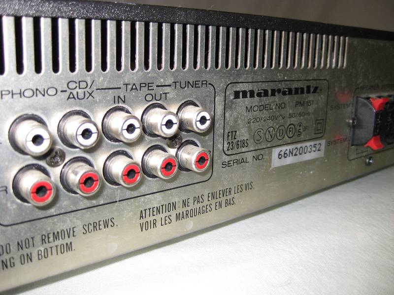
My amp (a marantz now nearly 20 years old) has started to cause my speakers to crackle to a point where they are un-usable.
I'm a student in the music production field, so my speakers are monitor speakers. KRK 9000b's, Mid 90's monitors.
They're fantastic speakers, but The amp is a Hi-Fi amp. Not the best thing for the job.
People have recommended me a Bryston, which as you'll know are very expensive, and something I can't afford right now, so I've been using this amp since I started.
Over time, though, this crackling has gotten worse.
First it was only on one Chanel on and off, and then it's spread to all of them and gotten worse.
Before It'd go off after a while, and now it's there pretty much all the time, occasionally letting a clean signal through for five minuets before reverting.
I've been told it's likely a problem with the capacitors leaking, but that was all the person could tell me other than "perhaps you should get a new amp"
as said before, Hi-Fi amps aren't the best for music production and for use with monitors, some even saying they can damage the tweeters at high volumes (how true that is I don't know), but I just can't afford a proper power amp right now.
On the flip side, good class D amps, though cheap comparatively, are expensive for me also, and to drop £250 on something that might damage the speakers and isn't good for them is a hard pill to swallow.
So, I was wondering weather the issue was repairable?
Can the capacitors be replaced?
Thanks allot.
Welcome to diyAudio 🙂
Electrolytic capacitors do deteriorate with time and particularly high temperatures but they wouldn't perhaps be the first suspects.
I would check the amp thoroughly for any poorly soldered joints, particularly around any hot running components. Look closely around the driver and output transistors. Driver transistors can fail intermittently but you would be unlucky to have the problem appear on both channels.
Other possibilities are the speaker relay. Usually this shows up as a fault that 'improves' if you turn the volume up.
And make sure any switches and controls operate without crackling as they are operated. If the amps gets a lot of action around the input sockets (constant plugging and unplugging) then check these for poor soldering as well.
Good luck 🙂
Yes, crackling after some runtin would induce thermal problems within the amp - maybe, as said by Mooly due to cold solder joints. Is there any crackling even when fully muted? Does the crackling is knock-sensitive? Does the crackling goes away when the (openend) amp is forced cooled?
Welcome to diyAudio 🙂
Electrolytic capacitors do deteriorate with time and particularly high temperatures but they wouldn't perhaps be the first suspects.
I would check the amp thoroughly for any poorly soldered joints, particularly around any hot running components. Look closely around the driver and output transistors. Driver transistors can fail intermittently but you would be unlucky to have the problem appear on both channels.
Other possibilities are the speaker relay. Usually this shows up as a fault that 'improves' if you turn the volume up.
And make sure any switches and controls operate without crackling as they are operated. If the amps gets a lot of action around the input sockets (constant plugging and unplugging) then check these for poor soldering as well.
Good luck 🙂
Thanks for the reply.
I'll go check the things you mentioned and see if I can get any closer to solving this.
Yes, crackling after some runtin would induce thermal problems within the amp - maybe, as said by Mooly due to cold solder joints. Is there any crackling even when fully muted? Does the crackling is knock-sensitive? Does the crackling goes away when the (openend) amp is forced cooled?
Thank you for the reply.
There's no crackling when the amp is muted, cracking isn't knock sensitive, and the crackling doesn't go away when the amp is opened and the circuitry is exposed.
Forced cooling is still missing. 🙂 Muting is done via volume-knob? Had an amp for repair lastly which dropped sometimes - it was the failed main switch (internally loose connection).
Simple to check -> unplug the amp and rapidly push all lever-switches many times. Plug back in and see if it helped. If it didn't, we have to look further.
Simple to check -> unplug the amp and rapidly push all lever-switches many times. Plug back in and see if it helped. If it didn't, we have to look further.
Last edited:
Forced cooling is still missing. 🙂
What do you mean by force cooling? What does that entail?
What do you mean by force cooling? What does that entail?
Just had a look online and couldn't fine anything on it, thanks.
What do you mean by force cooling? What does that entail?
Utilizing a fan to cool the components. You'd said that the crackling takes some minutes from power-on to occur, so we want to check if it's a thermal problem. (sound/looks like)
So I checked the things you suggested, mooley.
First off, I don't think it's the speaker relay thing you mentioned - the problem does not get any better when the volume is turned up, in fact, I think it gets worse.
This may be though because the problem is going to sound worse at a high volume anyway, however.
The transistors you said to check for bad souldering appear to be obscured by the circuit board, the pins going into the board and underneath somewhere.
I'll be uploading some pictures tonight of the amps Inards and outsides, that I'd be very greatful if you could have a look at.
Thanks!
Doctormored - I'll try placate a fan to try that.
It doesn't always take a few minuets to start cracking - that happens when the amp is powered on, and on the odd occasion it procduces a clean signal.
What I meant was that the clean signal doesn't last long when it does this, and soon reverts back to its original state - sorry for the confusion.
I'll try the thing you mentioned with the muting - i must ask though, what exactly are lever switches? Had a look online and couldn't find anything.
Thanks!
You do need to look visually at all the soldering on the board. This image shows a typical dry. Look at the middle leg of the transistor and how the solder has cracked around it.

You do need to look visually at all the soldering on the board. This image shows a typical dry. Look at the middle leg of the transistor and how the solder has cracked around it.
Thanks for the image, I see what you mean.
I've been trying to upload the photo's of my amp, but the up-loader isn't letting me.
It said to contact admin which I have done.
Perhaps it's something to do with me being a new member.
Hopefully I can upload soon.
The problem I have is that I can't see any solder points or a way to get to them. the circuit board seems to be flipped over, so the side with all the solder on is on the bottom.
EDIT: Attachments have worked now.
Last edited:


Found these online.
Unfortunately there were no circuit shots, so they probably help zero.
Something I did manage to find though was this:
Marantz PM151 Service Manual free download,schematics,datasheets,eeprom bins,pcb,repair info for test equipment and electronics
There's a PDF at the bottom of the page you can download, and when I did, it gives you the schematics for the system.
Cheers.
Hmm. Not quite what I was expecting.
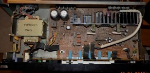
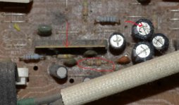
I've not been able to turn up a service manual for this, however the circuit in this one appears to be based around a 'driver IC' that replaces what would normally be a handful of separate transistors and so on. The resistor circled also looks slightly discoloured has if it runs hot.
You might get lucky and find that the IC has developed dries on the soldering of it, more likely at this stage is that it could well be a problem with that IC.
Hard to make out in a picture but just make sure the top of that upper cap in the group of four is 'flat' on top. Has the top split upwards ? The slits are normal, they are safety vents, but the top should be flat.
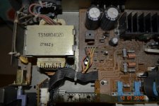
Attachments
Hmm. Not quite what I was expecting.
I've not been able to turn up a service manual for this, however the circuit in this one appears to be based around a 'driver IC' that replaces what would normally be a handful of separate transistors and so on. The resistor circled also looks slightly discoloured has if it runs hot.
You might get lucky and find that the IC has developed dries on the soldering of it, more likely at this stage is that it could well be a problem with that IC.
Hard to make out in a picture but just make sure the top of that upper cap in the group of four is 'flat' on top. Has the top split upwards ? The slits are normal, they are safety vents, but the top should be flat.
Right I see, thanks.
The capacitor is flat, none are split upwards.
Hmm. Not quite what I was expecting.
I've not been able to turn up a service manual for this, however the circuit in this one appears to be based around a 'driver IC' that replaces what would normally be a handful of separate transistors and so on. The resistor circled also looks slightly discoloured has if it runs hot.
You might get lucky and find that the IC has developed dries on the soldering of it, more likely at this stage is that it could well be a problem with that IC.
Hard to make out in a picture but just make sure the top of that upper cap in the group of four is 'flat' on top. Has the top split upwards ? The slits are normal, they are safety vents, but the top should be flat.
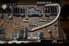
So the rectangular black part is the driver IC?
Yes, the IC appears as though it will contain most of the circuitry.
Does it have a type number on it ?
Does it have a type number on it ?
Yes, the IC appears as though it will contain most of the circuitry.
Does it have a type number on it ?
Just checked, and upon close inspection the chip has written on it on one side
"NEC" and then a long number.
It also has "Japan" written on it separately.
NEC could refer to the Japanese electronics company, perhaps?
Japan would obviously mean the place it was manufactured in, Marantz been a Japanese company, which could also mean replacement parts being difficult to get hold of.
I've found marantz often seem to use bespoke parts.
Not sure what the number is..
- Status
- Not open for further replies.
- Home
- Amplifiers
- Solid State
- Problem with amp: Crackling?