I got it from a friend 2-3 months ago. Tested the tranzistors with my multymeter and they looked fine.
Hooked it up now for a test run and surprise...nothing comes out. Fan stars spining, green light on the LED...yet nothing comes out the speaker.
First request could be...can I get some service manuals pls? `cause I can`t find none.
Second question...can someone guide me along the proces of trying to repair it ???
What should I search / look out for ?! First thing I`ll do in the morning is test out the transistors. And will keep you posted.
Cheers
Now...I checked the tranzistors again. set the multimeter on Diode mode, and checked them...no problems as far as I can see.
Please tell me what to check / do next .
Cheers
Please tell me what to check / do next .
Cheers
ok. status update.
led power up (Green). current goes in it. but still no sound.
a piece of advice would help.
thx in advance
led power up (Green). current goes in it. but still no sound.
a piece of advice would help.
thx in advance
I have no information on this amp and could not find a free service manual. If you can locate a copy of the service manual and post or send me a copy, I'll try to help.
I have no information on this amp and could not find a free service manual. If you can locate a copy of the service manual and post or send me a copy, I'll try to help.
Attachments
I have found the solution to the problem at the absence of sound
The problem to the absence of sound is this:
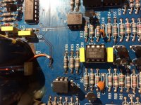
the fault is the absence of power in the IC U5. the communication has broken like a fuse, we have to put that communication back together. a simple cable will connect +12 to pin 1 Like a photo
The problem to the absence of sound is this:
the fault is the absence of power in the IC U5. the communication has broken like a fuse, we have to put that communication back together. a simple cable will connect +12 to pin 1 Like a photo
Attachments
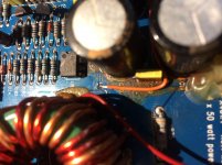

That fixative around the capacitors has broken down. When it does, it becomes both conductive and corrosive and must be removed.
The problem to the absence of sound is this:
the fault is the absence of power in the IC U5. the communication has broken like a fuse, we have to put that communication back together. a simple cable will connect +12 to pin 1 Like a photo
Thanks adrian74 for the tip! This appears to have resolved the issue with my amp. How did you ever figure this out?
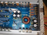
I followed your instructions to assert +12v to pin 1 of IC U5. I didn't solder a jumper directly to the PCB though. I wrapped one end around the leg of pin 1 on the IC and soldered. On the other end, I wrapped it around the remote power (input to amp to remotely switch it on) and soldered. I'm not sure how much power this IC draws and if it won't work correctly getting its supply from the remote power pin. I did it this way because it was easy and I didn't want any parasitic draw. The amp worked on my bench successfully. Now it is time to reinstall to the boat.
Thanks again! You saved the day.
Attachments
I just looked at the datasheet for IC U5. This is a 4N25 phototransistor coupler. It looks like pin 1 only drives an internal LED for the optocoupler, so this pin should have minimal power draw. I feel better now that I wired it to the remote power switch. Should not have any ill effect.
- Home
- General Interest
- Car Audio
- Problem with a Clarion APX 401.4 ! NO SOUND