Hi everyone,
Some background.... I've built a 5.1 channel surround amplifier for my PC using three Burr-Brown PGA2310 digitally controlled pots to adjust the volume.. The SPI control signals are produced using a Xilinx CPLD in response to inputs from my up/down volume switches.
It kinda works but one of the PGA2310s almost always produces a nasty DC offset on it's outputs whenever the gain value changes from 128 to 127!! It's always the same device (which controls the center and LFE channels) and the problem goes away as soon as I flick the up switch to return the gain value to 128. The other two PGA2310s have never showed this problem.
The signal timing is shown below. That's a 5ms/div timebase - could the timing be too slow?!
Any thoughts? Could it be a faulty device?
EDIT: I forgot to mention that all three PGAs have their SPI signals paralleled, not daisy chained.
Nice one,
David.
Attachments
Hi,
Im working with 5.1 setup also, but with CS3310 and PIC16F877A. I cannot see any problem in that picture, there is enough time between CS --> 0 to first clock pulse and so on. Can you get picture when code is 127? If that seems to be right, controlling is maybe ok. If i remember right, at reset CS3310 output is 1/2 Vcc, so maybe chip is resetting if there is DC at output??
If i look datasheet right, low speeds wont be any problem, lowest clock speed is 0Hz.
- Mika
EDIT: I just remember that ZCEN-function. There is some kind of 18ms timeout circuit if ZCEN is enabled, maybe u should try to disable zero crossing function because controlling is quite slow?? This is just quessing....
By the way, very nice looking amp. There is poweramps also at saem board? 5 x LM1875?? do u have any display in your system?
My setup is something like this:
PIC16F877A controlling everything, 3xCS3310 pots, HD44780 LCD, HT12A/D for remote controlling and input buffers of course. I build some kind of menu-system, where user can adjust every channel levels and some other things like where sub-channel input comes (from LFE-channel or from MAIN-channels). Software is fully working now, and i have just runned about 50 hours tests with prototype. Now im working with PCB's, exatly they are ready but i have some problems with SMD components delivery.
I have also DIY poweramp, it uses 5xLM3875. Subamp is ESP projects bridged P3A.
- Mika
Hello Mika,
Thanks for your input.
I've attached a scope plot showing the offending 127 gain value and, as you can see, it's exactly as expected with HUGE set-up & hold times and everything well within the part's specification.
I'm not sure what you mean by the reset function. The PGA2310 doesn't have a reset pin and I believe it's pin compatible with the CS3310 so you shouldn't have a reset pin either!
The ZCEN function is currently enabled. I'll try disabling it.
I think the chip has to be faulty but I don't really want to request any more free samples from TI. I originally requested three PGA2311 (the +/- 5v version) by mistake and they popped as soon as I put +/-15v onto them. I put in another request for three PGA2310s while cursing myself for not checking the part number. I think a third request is abusing the free samples program!
Does anyone know a source for the PGA2310 in the UK?
Nice one,
David.
Attachments
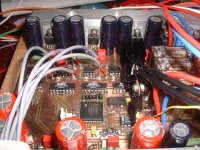
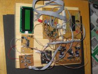
To answer you other questions, the power amps are all onboard and consist of five TDA2050s for front/center/rear and two LM3668s to drive a dual VC sub. The sub channel also has a 20Hz low pass filter and a Linkwitz Transform to boost the bass.
The pic below shows a bit more. You can just about see the seven power amps and a pair of 2N3055/2N2955 to reduce the +/-32v subamp supplies to +/-24v for the TDA2050s. Physically it's like a plate amplifier which is bolted to the rear of the sub. The two aluminium bars connect onto a "bloody big" heatsink on the back.
The whole project sounds really good, as long as I don't reduce the volume too much! The bass is fantastic considering it's only an 8” driver in 25 liters sealed. The sub only bottoms out if I play it really loud.
The only display I have in my system is an LED!
It sounds like you have quite a project there. How long has it taken so far? What complier are you using for the PIC? I'd like to learn how to use PICs as CPLDs are very limiting for control applications.
Attachments
Hi!
I have used assembler language to program PIC, its maybe the hardest way but i think that way source code is fully free from bugs and i know exatly what every instruction do. I started my project about 4 months ago, but school has take almost all my time last 2 months.
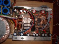
I hope that my preamp is ready in next 2 months. I attached one picture of my prototype (NOT-SO-NICE-version) 😀 . There is only 2 channels on that board. I will report more to here forum, when i got preamp finished.
And yes, maybe that one PGA is broken. And yes, i remember wrong there is no any external reset, only thing to do was keep MUTE-pin active more than 100us on a start up (if i can remember even that right 🙂
Have u made that PCB yourself?
I have used assembler language to program PIC, its maybe the hardest way but i think that way source code is fully free from bugs and i know exatly what every instruction do. I started my project about 4 months ago, but school has take almost all my time last 2 months.
I hope that my preamp is ready in next 2 months. I attached one picture of my prototype (NOT-SO-NICE-version) 😀 . There is only 2 channels on that board. I will report more to here forum, when i got preamp finished.
And yes, maybe that one PGA is broken. And yes, i remember wrong there is no any external reset, only thing to do was keep MUTE-pin active more than 100us on a start up (if i can remember even that right 🙂
Have u made that PCB yourself?
Attachments
Case solved.
I've done a little more investigation over the Christmas break....
When the gain is set to 128 (-32dB), the DC offset on all three PGA2310s is less than 1mV. When the gain is reduced from 128 to 127, all three chips show a jump in offset but the 'good' chips only are one or two milivolts whereas the 'bad' chip is almost 12mV, on both channels. I'm guessing the internal gain setting resistors are poorly matched in this particular part.
The power amps are all DC coupled to the PGA2310. The amps have a gain of x30 so the offset gets amplified and the Linkwitz Transform for the sub has an additional DC gain of x4 so that 12mV offset becomes 1.4v at the driver!
The bad PGA2310 does not meet spec (data sheet says 3mV offset max with the input grounded and gain set to 0dB) but it seems to work okay otherwise so I guess I'm going to have to squeeze some DC block capacitors in there somewhere....
To answer your question, I designed the PCB using the Proteus suite from Labcenter (very good software - recommenced). I laser printed the design onto Press 'n Peel then etched in ferric chloride. The PCB is doubled sided and it's quite awkward to align the top and bottom layers but it allows much better routing, especially considering I've got three ground planes (digital, analogue signal and analogue power).
Your project looks very ambitious! Good luck.
And remember to fit those DC blocking capacitors!
I know its an old thread, sorry to wake this up again.
Hi Daatkins,
Did you manage to overcome the pga2310 DC offset noise?
If yes, can you please tell me what you did?
Thanks in advance,
Isak.
Hi Daatkins,
Did you manage to overcome the pga2310 DC offset noise?
If yes, can you please tell me what you did?
Thanks in advance,
Isak.
Hi there Isak,
It be honest, this happened so long ago that I can’t remember what I did, but I don’t think I ever got to the bottom of the problem…
The PCB photo that I included in the second post was soon superseded by a second version due to a couple of other problems and I know I included low pass filters between the three PGA2310s and the power amp inputs on this updated version. This would have solved the problem but I think the underlying cause was probably a bad chip.
Are you seeing exactly the same thing?
Hi there Isak,
It be honest, this happened so long ago that I can’t remember what I did, but I don’t think I ever got to the bottom of the problem…
The PCB photo that I included in the second post was soon superseded by a second version due to a couple of other problems and I know I included low pass filters between the three PGA2310s and the power amp inputs on this updated version. This would have solved the problem but I think the underlying cause was probably a bad chip.
Are you seeing exactly the same thing?
thank you for replying 🙂
well its not exactly the issue in my case.
i'm not using the PGA2310 for preamp or amp, using it only as attanuetor, going from -95dB to 0dB, meaning i'm not using all the 255 steps, only 204 steps which is 0dB.
i think i know what is my problem but i dont know how to fix it.
i'm using arduino uno, PGA2310 and 100k regular analog pot to control the PGA2310 via arduino.
i think the problem is the analog read (A0 input in arduino) of the analog pot.
when turning the pot all the way up and down i can hear clicks pops in the my studio speakers.
when i tested the digipot using a code that all its doing is going up and down automatically, it went from -95dB to 0dB smoothly, no clicks, no pops.
when try to control it via analog pot i get the issues above.
i was watching the arduino moniotr screen running the numbers i could see that when i'm turning the analog pot fast it jumps between values and not going thru all the values, meaning....say i'm in -95dB, turning it fast CW, i get -89..-83...-75...and so on, its like ...missing the values in between.
i think thats what makes the clicks and pops.
i need to find a way for it to go smoothly thru all the values as fast as i turn the analog pot.
i put 100nF from A0 to GND to soften the read, no luck.
the scheme i use is the same as TI present in the datasheet, no more no less.
i dont want to use encoder cause if i i'll use encoder i will need a lot of turns till i'll get max volume cause its going thru every step (0.5dB every step).
in addition, its funny that you say you got noise between 127-128 step, i get some sort of strong click/pop when going thru this step.
sorry fro the long post.
cheers 🙂
Hi isakeliyahu,
Don't be afraid of the encoders. They work well. You need 64 pulse two channel encoder. It will do 256 steps in one revolution.
Regards,
Oleg
Don't be afraid of the encoders. They work well. You need 64 pulse two channel encoder. It will do 256 steps in one revolution.
Regards,
Oleg
The PGA2310 needs to be AC coupled to the input for the zero crossing option to work, otherwise it will click and pop on volume change.
Hi isakeliyahu,
Don't be afraid of the encoders. They work well. You need 64 pulse two channel encoder. It will do 256 steps in one revolution.
Regards,
Oleg
thank you Oleg 🙂
good to know!
The PGA2310 needs to be AC coupled to the input for the zero crossing option to work, otherwise it will click and pop on volume change.
but the zero crossing is from 0dB up to 31.5dB if i'm not mistaken.
its only when i amplify, i dont need to amplify, only to attanuate.
from -95dB to 0dB.
you say to try putting an...say 100nF in each input of the PGA2310?
Btw, the pops and click happens even when nothing is connected to the input.
Last edited:
Try putting a 10uF cap in series with the input.
I thank yoy for your input, but you really think it will be matter that ill connect 10uF in series when no signal is connected to inputs and still get clicks and pops?
Thanks again for the help!
Your problem does sound like a software issue. It doesn't hurt to connect things properly though. You should also be using pull ups on the data lines and a pull down on mute to avoid the lock up/melt down issues too.
As Oleg has mentioned, encoders can be use with the Arduino, but if you plan to use a LCD display with it, they can drop a lot of input readings.
Linuxworks is putting together very efficient software to read a 380 Res encoder with a LED display. He's been showing some of his work in the AMB Forum. AMB Laboratories DIY Audio • Index page
thanks for the input, your are right in your way of thinking, i'll do that.
i'll gonna use oled display.
do you by any chance have a recommended encoder that you have experience with?
how about next one....
ENA1J-B28-L00064L | Bourns 64 Pulse Optical Encoder with a 6.35 mm Round Shaft, Bracket Mount | Bourns
the right way to connect the encoder to the Arduino (i found a lot of ways to do it over the web, non of them was smooth, even when debouncing in code and components).
maybe a scheme or a code?
really appreciate the help, thanks again.
i'll gonna use oled display.
cool, looks interesting, thank you.Linuxworks is putting together very efficient software to read a 380 Res encoder with a LED display. He's been showing some of his work in the AMB Forum. AMB Laboratories DIY Audio • Index page
do you by any chance have a recommended encoder that you have experience with?
how about next one....
ENA1J-B28-L00064L | Bourns 64 Pulse Optical Encoder with a 6.35 mm Round Shaft, Bracket Mount | Bourns
the right way to connect the encoder to the Arduino (i found a lot of ways to do it over the web, non of them was smooth, even when debouncing in code and components).
maybe a scheme or a code?
really appreciate the help, thanks again.
we've been experimenting with some industrial encoders. They feel a whole lot smoother that the Bourns product, and are readily available.
360RES Rotary Encoder A B 5 24V D38MM | eBay
360RES Rotary Encoder A B 5 24V D38MM | eBay
Last edited:
- Status
- Not open for further replies.
- Home
- Amplifiers
- Solid State
- Problem controlling a PGA2310