When it comes down to it, you would have to model the entire crossover network (bass, mid & treble) to see how well the drivers integrate.
Above my pay grade I'm afraid! 🙁
Above my pay grade I'm afraid! 🙁
you could not help me?
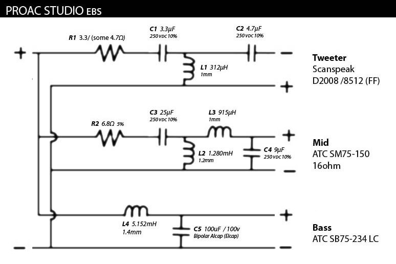
This is the original scheme with the medium of 16 ohm and mine that I got is 8 ohm
This is the original scheme with the medium of 16 ohm and mine that I got is 8 ohm
Looking back at your first post, you don't actually say what you find wrong with the performance of the 8 ohm version of the midrange driver.you could not help me?
You mentioned that a 'Wilmslow Audio crossover' gave a worse result than the original manufacturer's 16 ohm midrange crossover.
That begs the question - in what way is the replacement 8 ohm midrange speaker underperforming when used with the original 16 ohm crossover?
Why not accept the help you've already been given and physically try out Datsun's crossover modification to see if it remedies matters?
I already experimented with this design by dividing and multiplying components and the best one sounds great and putting the 15uf capacitor and not the 4.7uf capacitor is not because if it is not superior.
Would I have to put the 4,7uf is my question?
Would I have to put the 4,7uf is my question?
There appears to be a problem of communication here, perhaps due to language differences.
It is not clear which crossover version you think is 'best'.
Also, if the 'best' crossover 'sounds great', what is the problem?
We need a drawing of this 'best' crossover, including the component values.
Then perhaps we will better understand your question regarding the 4.7uF capacitor.
It is not clear which crossover version you think is 'best'.
Also, if the 'best' crossover 'sounds great', what is the problem?
We need a drawing of this 'best' crossover, including the component values.
Then perhaps we will better understand your question regarding the 4.7uF capacitor.
I think I understand now, but correct me if I'm wrong!
It seems that you have used the 15uF capacitor instead of the recommended 4.7uF one because you think it makes the crossover sound better.
If that is the case then stay with the 15uF capacitor. You don't have to use a 4.7uF capacitor just because the rules say so. Often, breaking the rules gives the best result!
I haven't tried the 4.7uf one, I'm just using the one in the scheme.
I don't know what the result would be to put half the capacity of the original scheme of Galu
I don't know what the result would be to put half the capacity of the original scheme of Galu
4.7uF is the recommended value to use in the crossover circuit you show in post #26.
Just try it, you won't break anything!
What more can I say?
Just try it, you won't break anything!
What more can I say?
Crossover proac ebs
I think that you are living the value of the twteer 4.7uf and not the medium that is 15uf
I think that you are living the value of the twteer 4.7uf and not the medium that is 15uf
The capacitor in parallel with the ATC SM 75-150 shown in post #26 should be 4.7uF and NOT 15uF.
WAIT A MINUTE!
I've just spotted a mistake in one of Datsun's component values in post #10, which I've been wrongly working with!
The rule is that if the driver impedance is halved then the inductor value should also be halved and the capacitor value should be doubled.
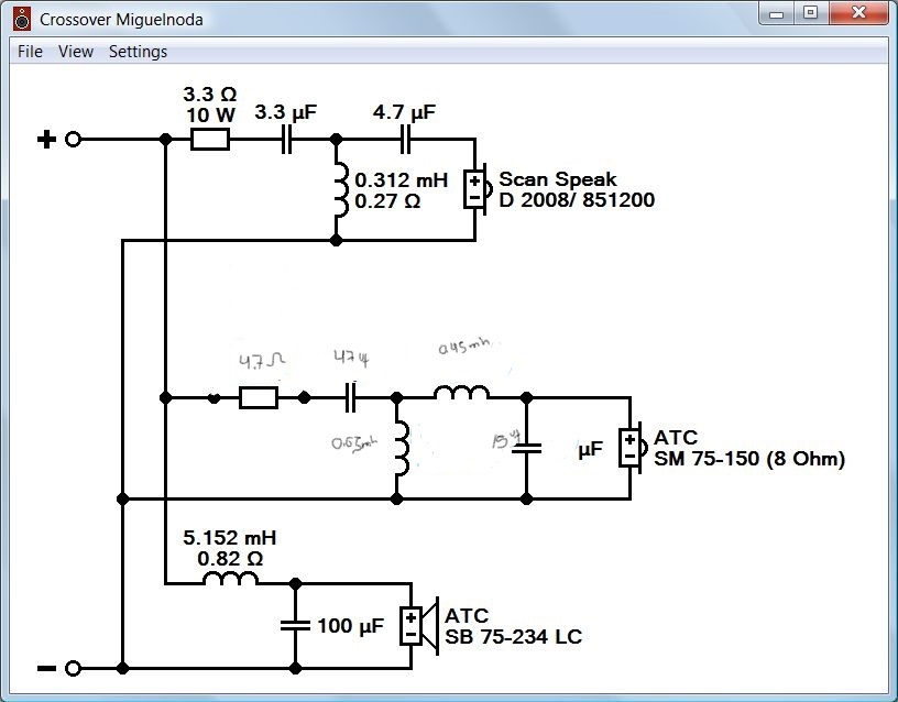
Thus, referring to the original crossover scheme the midrange components should be changed to:
C3 = 47uF, L2 = 0.65mH, L3 = 0.45mH and C4 = 18uF
So its neither 4.5uF or 15uF, but should be 18uF.
Hope this finally clears things up!
I've just spotted a mistake in one of Datsun's component values in post #10, which I've been wrongly working with!
The rule is that if the driver impedance is halved then the inductor value should also be halved and the capacitor value should be doubled.
Thus, referring to the original crossover scheme the midrange components should be changed to:
C3 = 47uF, L2 = 0.65mH, L3 = 0.45mH and C4 = 18uF
So its neither 4.5uF or 15uF, but should be 18uF.
Hope this finally clears things up!
Attachments

P.S. Since 18uF is not a standard value, you will have to approximate it by wiring two capacitors in parallel e.g. a 10uF and an 8.2uF.
Or, more sensibly in your case, put a 3.3uF in parallel with your existing 15uF!
Please let me know how it goes.
Please let me know how it goes.
C3 = 47uF, L2 = 0.65mH, L3 = 0.45mH and C4 = 18uF
Sorry, this is my typo - the shunt capacitor should be two times the nominal value - 18 μF. ((
I sometimes use LC_Filter.
Crossver proac ebs
The crossover in the middle and lower part works very well with these new values but the upper part sounds advanced and with sound as distorted or with grain I would like to attenuate or sound without being ahead of what I could do, insert some resistance?
The crossover in the middle and lower part works very well with these new values but the upper part sounds advanced and with sound as distorted or with grain I would like to attenuate or sound without being ahead of what I could do, insert some resistance?
If the treble is too strong, then try increasing the value of the tweeter resistor R1 to 4.7Ω.
A higher value such as 5.6Ω or 6.8Ω may be necessary - work your way up if required.
If that proves unsatisfactory, then report back.
A higher value such as 5.6Ω or 6.8Ω may be necessary - work your way up if required.
If that proves unsatisfactory, then report back.
You want the sound to be the same as the original...
I think you should leave the woofer and the tweeter crossover original. Then compare the 8 ohm and 16 ohm response so you can create the difference. You must also compare the 8 ohm and the 16 ohm impedance vs frequency. This is much easier to do with a simulator.
I think you should leave the woofer and the tweeter crossover original. Then compare the 8 ohm and 16 ohm response so you can create the difference. You must also compare the 8 ohm and the 16 ohm impedance vs frequency. This is much easier to do with a simulator.
crossover proac ebs
the sound with that grain in the high part was suspicious to me that the d2010 were distorting I had the opportunity to try others and they no longer do it, I think that with the Wilmslow Audio filter they lowered the frequency cut a lot and broke down.
now they work well but I would like to put some better twetter
They could advise me with the same characteristics or modifying the croossover.
Cheers
Hello.
In order not to produce topics, I decided to ask knowledgeable people here: I purchased the used ProAc D30S acoustics
I noticed that there are fewer high frequencies in the left channel. The acoustics did not seem to open.
Using improvised means, I took off the amplitude-frequency response, in the area of the tweeter the difference is 2dB.
Question: Is such a channel mismatch acceptable? Can this be fixed by reducing the resistance of the resistor? Is this a defect from the factory or the previous owner ruined the acoustics?
Thanks.
- Home
- Loudspeakers
- Multi-Way
- Proac crossover