Great, thanks for that. I've measured input voltages of 40.1v on REG1 and 41.2v on REG2. Is that good?
Voltage imbalance. In the shoulder, where the voltage is lower, the load current may be greater. Or less capacitance.
Great, thanks for that. I've measured input voltages of 40.1v on REG1 and 41.2v on REG2. Is that good?
At face value it's no good. If those are the input voltages then they are to low. To get 40 volts regulated output, the input need to be higher by a few volts.
I assume the output voltages were correspondingly lower and in that condition the regulators do not work and just pass the noise and ripple through.
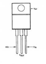
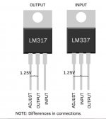
Also if you look at the circuit diagram I posted earlier you can see it appears to have an error in the pinouts of the negative regulator which is different to the positive one.
Attachments
Sorry I've double checked these readings and I was measuring the wrong pins. The correct readings are LM317 Input 61V Output 41.4V LM337 Input 59.2V Output 41.2V. Is that more like what you would expect?
No problem 🙂 but yes, it is more what would be expected, however a simple voltage reading doesn't tell us if there is any ripple there.
(One of the sets of those readings will be negative 😉)
In view of this I would suggest at least replacing those caps on a like for like basis if only to eliminate them. As mentioned before, this really does need a scope because we are guessing at possible/probable causes without hard evidence in the form of the required measurements.
The standard LM 317 has an input range to 40 volts although I see where
Mooly is coming from , only the LM317HV goes up to 60 Volts-
LM317 3-Terminal Adjustable Regulator datasheet (Rev. Y) - lm317.pdf
Mooly is coming from , only the LM317HV goes up to 60 Volts-
LM317 3-Terminal Adjustable Regulator datasheet (Rev. Y) - lm317.pdf
That's odd. I've double checked again and there are definitely 59v going in. Could that be because some of the caps in the voltage doubler are the wrong values?
Its the shape of the circuit that matters and in a standard voltage doubler circuit a slight variation in capacitance wouldn't matter .
What really matter is the working voltages of the capacitors should be TWICE the peak of the input voltage --now that does matter.
What really matter is the working voltages of the capacitors should be TWICE the peak of the input voltage --now that does matter.
So would that mean the 50v caps in that circuit may be the issue as they are rated below the 60v? I’m planning on replacing them and if that doesn’t work I’ll get hold of a scope and investigate further.
Its a technical truth that a voltage doubler circuit requires higher voltage capacitors don't take my word for it check it out for yourself.
We can work back to see what to expect. The main rails are -/+40 volts DC and so that means the AC voltage on the transformer is approx 28 volts rms.
28 volts AC applied to that doubler will give 80 volts DC off load. To pull the voltage down to 60 volts needs a load current of around 10 milliamps if we use 10uF and 100uF.
If we increase the 10uF cap to 47uF we see the DC voltage rise to around 73 volts for the same current draw. The current draw in the real amp is an unknown though. It must be around that value, otherwise the rails would collapse.
The 10uF cap sees 40 volts across it.
If you consider the positive regulator then as the input cycle rises to 40 volts the other end of the cap limits at about 60 volts because of the small cap value limiting the current available.
As the input cycles goes negative (nothing to do with the negative regulator) the voltage across the cap is 40 volts because the diode clamps one end of the cap to ground. the other end falls away to 40 volts at the negative peak of the AC cycle.
The reservoir cap sees the full DC voltage of the doubled supply, so theoretically 80 volts.
Now there lies a clue. If those 100uF caps are 63 volt rated then the circuit is relying on the 10uF as a limiting factor together with those series resistors.
So I would replace like for like just to eliminate them from suspicion. Replace all 4 caps.
I do not completely agree to encourage somebody
who is "not that familiar with electronics" to do SMD
equipment repair.
who is "not that familiar with electronics" to do SMD
equipment repair.

So it was the capacitors in the voltage doubler circuit ?
I see where AS_audio is coming from , better with the right equipment + experience with solder flow in SMD components.
In any case I am glad DIY Audio posters managed to help you to a positive result.
I see where AS_audio is coming from , better with the right equipment + experience with solder flow in SMD components.
In any case I am glad DIY Audio posters managed to help you to a positive result.
Yes I assume it was the caps. This was all I replaced. There was quite a lot of damage to the pcb that had been messily repaired. I left all that alone.
Mended- id 😉 Excellent, I'm pleased it was an easy fix in the end. Voltage doubler arrangements are common in lots of equipment and the caps generally have a very tough time as they pass significant current.

- Home
- Amplifiers
- Solid State
- Primare A20 Amplifier Hum