Hi, I have an old Primare A20 that’s been working fine for many years. Recently it’s started to hum through the speakers. The noise sounds like ground hum and is there even with no inputs connected and doesn’t vary with the volume. The sound is the same through both channels. I’ve checked and all the ground connections are fine. Is there a particular component that could cause this issue?
Nice amp like the Swedish style was expensive in its day , just a word of warning ---
You are not alone a Canadian guy is selling his ,he recapped it but still has "slight hum " even so it sold okay.
Do as OldDIY says but use the most expensive replacements you can afford not necessarily a big increase in capacitance much more an increase in quality .
This is a good amplifier.
Just seen your photo and I am right they aren't top end capacitors this amp is well worth repairing.
Yes that would be those capacitors.
Last edited:
Thanks. I'll get those changed. There are also a couple of caps on the board feeding the transformers. A filter capacitor, what looks like a couple of tantalums and an electrolitic. Could they be a source of the noise as well?
Yes you can change the filter capacitor , if it is an old film capacitor change it for a modern FILM FOIL polypropylene one --not a metalised one also change the electrolytic .
Tantalum capacitors are usually quite reliable so leave changing them to last .
Your amp is worth the best quality capacitors forget about price .
After changing one set always try it first before you move on to change the rest this cuts down any errors being made.
I always liked Swedish design - cutlery/ old phones / chairs/etc there used to be a Swedish design centre in the city I grew up in.
Thanks. Would you recommend Nichicon LKGs? You're right about the design. It a nice amp just to use as a piece of furniture!
This amp seems to use separate supplies for each channels power amp, at least for the high current side of things. I wouldn't be to quick to condemn those large reservoir caps just yet.
Ideally you should be diagnosing this with a scope, however a couple of things jump out as possible problem areas and these are the voltage doublers used to derive the stable -/+40 volt supplies. The caps in the doubler would be prime suspects for failure as they lead a very hard life.
Ideally you should be diagnosing this with a scope, however a couple of things jump out as possible problem areas and these are the voltage doublers used to derive the stable -/+40 volt supplies. The caps in the doubler would be prime suspects for failure as they lead a very hard life.
Attachments
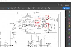
That does make sense. There are separate supplies for each channel so I wouldn't expect both to fail at the same time. I've had a look at that area on the schematic but it looks slightly different on my amp. There are 2 x 100uf 63v but also 4 x 10uf 50v. They all look in poor condition with what looks like heat damage on the outside. Ideally I would be doing this with a scope but will just replace all of them and see whether that helps.
Attachments
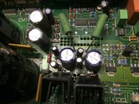
That photo tells everyone it's been repaired before.
Mainly between the heat sinks and the capacitors.
Its not quite clear, but to me it looks like extra smd resistors have been installed on legs.
There's also work done to the right of that area on the smd transistors.
I suspect the 'damage' to the caps is from a soldering iron barrel.
Mainly between the heat sinks and the capacitors.
Its not quite clear, but to me it looks like extra smd resistors have been installed on legs.
There's also work done to the right of that area on the smd transistors.
I suspect the 'damage' to the caps is from a soldering iron barrel.
Agree with Mooly, just had a repair like this on a
successor model with similar schematic last week.
successor model with similar schematic last week.
The cause may be a large quiescent current or a large bias of 0 after incorrect adjustment.
Check the line voltage for deviations and absence of surges and DC component. Neighbor welders.
Radio frequency interference on speaker wires (try with one short wire near).
Input hops through signal cables. Disable everything.
Pulse sources nearby (above and below) from the amplifier.
Check the line voltage for deviations and absence of surges and DC component. Neighbor welders.
Radio frequency interference on speaker wires (try with one short wire near).
Input hops through signal cables. Disable everything.
Pulse sources nearby (above and below) from the amplifier.
Well it definitely seems to have seen some rework in that area.
Only you know the history and whether the amp has been OK in the past and then failed gracefully over time.
It might be worth measuring the voltage going into and coming out of the regulators although that would not show ripple. If the voltages were low though...
Hard to tell from a picture but I wonder if those 'legs' are actually the leads of the caps that have been formed to follow the print, possible because the print has been damaged in a previous repair.
Picture : these four are replacements for SMD caps. See also :
Attachments
Last edited:
My dad used to own the amp and got it repaired about 15 years ago because the it wouldn't turn on. It's been fine since then and only started to hum in the last week. I've had a close look at the area and it looks like the 4 smaller caps have been replaced from above without removing the board and the legs have been used to follow the line of the print below. The heat damage could well be from a soldering iron.
I would just try and replace those caps then. Stick to similar values and use 105C specified parts of good commercial quality.
If the print has been damaged then it might be worth seeing if you can snip the old parts out and leave the 'linking' in place. In other words disturb as little as possible.
If the print has been damaged then it might be worth seeing if you can snip the old parts out and leave the 'linking' in place. In other words disturb as little as possible.
Yes I was thinking to disturb as little as possible. I'm confused as to why there are 47u 63v caps on the schematic and 10u 50v in the amp. I could only find a service manual for the I21 online which shows 47u 63v. If my caps are the wrong ones then they have the wrong capcitance and voltage rating.
The manual I looked at was for the A20 mk2 from HiFi Engine.
If there is doubt then measure the INPUT voltage to the regulator. Larger caps will increase that voltage and you don't want it to high.
I would suggest you tag some new 10uF's in there and measure the reg input voltage. You need at least 45 to 50 volts. If the 10uF fix the issue then swap them for a 22uF. If the voltage is little changed then fit the marked 47uF caps as a final replacement.
The LM317 type regulator have a 40 volt input limit but that isn't an absolute as it really means the input/output differential. I would play it safe though and get a feel for what is happening.
- Home
- Amplifiers
- Solid State
- Primare A20 Amplifier Hum