this makes sense about the phase. Because the woofer lags behind its signal, the feedback loop sends a much high voltage (should be infinite) to get the sluggish piece of mass to move more quickly. I am liking your results. How is cone excursion? Any chance of mounting the mic to the cone itself?
I did mount the microphone directly to the woofer.
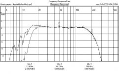
When I turn up the feedback it starts oscillating at 800 hertz, when I used a second order lowpass it started oscillating at 16 hertz, that's where the phase is 180 degrees out of phase because the woofer acts like a second order highpass.
I didn't really come up with a solution for that.
Phase response with feedback is flat from 40 hertz up though.
If it was oscillating at around 800 Hz then I'd really try the LAG filter instead of a simple lowpass. Furthermore I'd make the cap a little larger. You need most of your NFB at low frequencies.
Regards
Charles
Regards
Charles
There isn't much to gain from that as it will still oscillate at 16 hertz.
How do you come to this conclusion ? Did you actually try it ?
Regards
Charles
That's what it did with a second order lowpass, made from 2 10k resistors and 2 100nF caps.
Pherhaps I can take the output from IC1D, pass it through a lowpass and feed it to the inverting input.
Pherhaps I can take the output from IC1D, pass it through a lowpass and feed it to the inverting input.
Maybe it would make sense to put the LP filter after the microphone amp 1B and hence in front of the subtractor 1D?
The least it will do is keep higher frequency acoustic signals picked up by the mike from entering the subtractor and ending up in the loop that simply cannot deal with them.
The least it will do is keep higher frequency acoustic signals picked up by the mike from entering the subtractor and ending up in the loop that simply cannot deal with them.
BoBo1on1,
The 800Hz oscillation is because of the cone breakup resonance. I did a similar MFB sub (but using an AHC-01 accelerometer) and there was a huge peak in the woofer/accelerometer response at around the same frequency. I measured loop gain, and without EQing, that was the highest gain point and the phase moved fast through there, just about guaranteeing oscillation.
What I did to fix it (and what may work for you) is to put a passive Twin-T notch network, tuned to 800Hz, in the feedback path. With an integrator in the loop there was a region between about 300Hz and 700Hz where gain was reasonably far down, so the phase shift from the Twin-T sitting at a little higher in frequency didn't cause a stability problem. I also loaded the Twin-T with a smallish resistor (compared to the resistors in the T itself), which gave a bit of phase lead, so the notch ended up not hurting the phase much at all.
The MFB mod was done on a Dayton powered sub (with the ports blocked). Worked really well. There should be an article on this in AudioXpress in a few months...
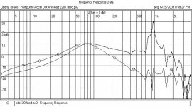
Here is a plot of the loop responses before and after filtering.
The trace marked by circles is the "after" (gains offset for comparison).
The "before" is what comes out of the accelerometer when driving the amplifier directly. The "after" is what comes out of the accelerometer when driving into the filter circuit where the accelerometer will connect when the loop is closed.
Attachments
Hi bwaslo,
I have a few questions.
Where and how did you mount the accelerometer?
The peak in FR at 1kHz looks to me like the resonance of the mechanical system consisting of the dustcap/accelerometer's mass .
Did you measure the THD?
Regards,
Milan
I have a few questions.
Where and how did you mount the accelerometer?
The peak in FR at 1kHz looks to me like the resonance of the mechanical system consisting of the dustcap/accelerometer's mass .
Did you measure the THD?
Regards,
Milan
>The peak in FR at 1kHz looks to me like the resonance of the mechanical system consisting of the dustcap/accelerometer's mass .
Could be. The sensor is glued to the dustcap (which is inverted). I figured the cone was flexing where the cap bonded to it, pretty far up from the voice coil.
I only made a cursory look at THD, it's about 1% (at 90dBSPL two feet) away down to about 30Hz, then climbs from 30Hz down till it is about 15% at 20Hz. Not amazing, but pretty good for under $200.
The original B&M used the same mic position as this Manger sub does:
http://www.manger-msw.de/images/produkt_abb/icon_subsonice_2_kl.jpg
It wouldn't be bad if bobo101 did a sweep of the driver-mic response as well. One doesn't have to be scared of phase-shift introduced by EQ networks if they really represent the complementary of an error with minimum-phase properties.
Regards
Charles
@all: Any opionion as to where the filter should be placed, in front of or after the subtractor?
@bwaslo: could you sketch your filter topology, please?
Thanks!
@bwaslo: could you sketch your filter topology, please?
Thanks!
Any opionion as to where the filter should be placed, in front of or after the subtractor?
After the subtractor IMO.
Regards
Charles
Just now I wondered why the bass was so loud when listening to the radio, it turned out I had my soundcard configured for bass redirection while using stereo spdif output.
So I don't need a shelving lowpass at the input.
The circuit is picking up interference from my wireless mouse though, I need some small caps at the input.
The microphone pics up sounds from my mains as well, but it is alot lower than the signal from the woofer.
The reason any filters should be after the subtractor is to get a sort of flat frequency response at the amplifier's output.
If a lowpass was placed before the subtractor the feedback circuit will make a shelving highpass at the amplifier's output, something you don't want.
What is your reasoning?
Since the error is in the forward path of the loop it is best corrected there.
Regards
Charles
Note that the Elektor example puts filtering right at the microphone. They have also configured the subtractor to work as a shelving integrator.
AT first sight, this looks like a double (2nd order) low pass, but I have the feeling that there is some lead compensation. Will have to plot the transfer functions at some point...
AT first sight, this looks like a double (2nd order) low pass, but I have the feeling that there is some lead compensation. Will have to plot the transfer functions at some point...
Here you can find an article from dutch elektor, they put the shelving lowpass at the microphone input and a second order lowpass at the output.
They used a piezo tweeter as an accelerometer.
I wonder what good the shelving lowpass does, except make the woofer go lower, except the woofer already goes very low due to positive feedback at low frequencies.
They used a piezo tweeter as an accelerometer.
I wonder what good the shelving lowpass does, except make the woofer go lower, except the woofer already goes very low due to positive feedback at low frequencies.
- Status
- Not open for further replies.
- Home
- Loudspeakers
- Subwoofers
- Pressure based motional feedback.