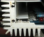
Any idea where to get the Mica strips for under the transistors? They were in pretty rough shape, removed them all.. was goona clean it up and redo the heatsink paste and mica as it was a mess
Couple other chips are not.looking so good with all the moving and bending (pins bout to break), was gonna replace those as well, they look pretty straightforward
LM7915CT and LM340T15
Must be regulators for the power supply?
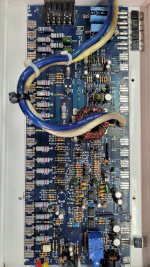
Board all cleaned up and ready for parts.
I assume 1/4 watt is fine for those 47 ohm resistors?
LM7915CT and LM340T15
Must be regulators for the power supply?
Board all cleaned up and ready for parts.
I assume 1/4 watt is fine for those 47 ohm resistors?
Attachments
I don't know what you're using to clean. Acetone is my favorite but it's not compatible with the powdercoat finish on PPI amps.
Those are regulators for the op-amps and other low-voltage circuits.
Various options.
If none of your insulators are usable...
https://www.mcmaster.com/products/mica/ Bottom of page, use the thinnest available.
Another option. Easier to cut and leave a nice edge. You don't want an adhesive backing.
https://www.mcmaster.com/2271K912/
Mouser/DigiKey have individual Mica insulators.
The cheap Kapton tape that a lot of people use will work but not as well as the ones above.
Those look good probably do the 2nd one. Just to confirm 1/4 watt for the 47 ohm resistors is what i shud get?
Thanks
Thanks
I'm sorry. I'm too caught up in something that's making my brain melt to pay proper attention.
Yes, 1/4w will be fine if they fit. 1/8 watt would also be OK in this application but wouldn't look right if the location is sized for 1/4w.
I like the Kapton. Use a straight-edge and a SHARP razor knife to cut it. Most people won't buy it, even after they regain consciousness (after seeing the price). It's my favorite replacement insulator. For the part you don't use, roll it up and put it where it won't get crushed.
Ok, so it looks like Mouser has everything I need so. I included the description and link of what was ordered. I will update once parts have arrived and been installed if this setup works properly!
Thanks
Mosfets:
IRF3205PBF
https://www.mouser.com/ProductDetail/Infineon-Technologies/IRF3205PBF?qs=2r01AXMCG3Ng8ivZ6KPoqw==
Resistors:
RNMF14FTC47R0
https://www.mouser.com/ProductDetail/708-RNMF14FTC47R0
Outputs:
2N6488G
https://www.mouser.com/ProductDetail/onsemi/2N6488G?qs=vLkC5FC1VN88NaKbi7kHTQ==
2N6491G
https://www.mouser.com/ProductDetail/863-2N6491G
Regulators:
LM7915CT/NOPB
https://www.mouser.com/ProductDetail/Texas-Instruments/LM7915CT-NOPB?qs=QbsRYf82W3F%2BRPQrGl%2ByOA==
LM340T-15/NOPB
https://www.mouser.com/ProductDetail/Texas-Instruments/LM340T-15-NOPB?qs=X1J7HmVL2ZFaklLItroQ3g==
Another option. Easier to cut and leave a nice edge. You don't want an adhesive backing.
https://www.mcmaster.com/2271K912/
Would you still use thermal paste with this Kapton? If so should it be applied to both sides?
Thanks
https://www.mcmaster.com/2271K912/
Would you still use thermal paste with this Kapton? If so should it be applied to both sides?
Thanks
Yes. You absolutely need heatsink compound, as you do with any hard insulators. Silpad or coated insulators are an exception to that.
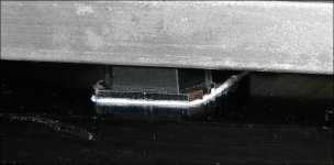
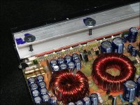
Yes. Both sides. I typically apply too much (for one surface) to the transistors. Lay the board in place and push all transistors down onto the heatsink. Then remove it and distribute the compound to cover the desired area. Confirm that enough is on the transistors and you should be OK. It doesn't need a flood of compound like PPI loves to apply. If you get good displacement that leaves compound all around the perimeter (about as is shown in the attached image), you have enough compound.
Yes. Both sides. I typically apply too much (for one surface) to the transistors. Lay the board in place and push all transistors down onto the heatsink. Then remove it and distribute the compound to cover the desired area. Confirm that enough is on the transistors and you should be OK. It doesn't need a flood of compound like PPI loves to apply. If you get good displacement that leaves compound all around the perimeter (about as is shown in the attached image), you have enough compound.
Attachments
So to clarify i should put thermal compound between the heatsink and kapton film. And between the component and the kapton as well. So coat both sides of the Kapton film?
It has to be applied to the back of the transistor and to the area between the insulator and heatsink that's beneath the transistor.
Update: Replaced all parts and turned the amp on. Installed 10A fuse on the input. Hooked up a small home theater speaker bridged to the output.
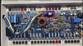
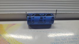
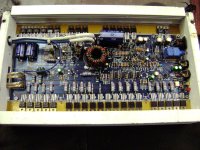
Turned gains up and played some music at 3/4 volume or so, all seemed fine heatsinks were not overly warm. This ran for about 4 to 5 minutes then blew the 10A fuse. I pulled the back cover off and found the large capacitor was completely blown off the board. 1 Mosfet and 1 Output transistor were also shorted. Please see attached for bad component locations marked in red. Picture for reference only (not taken at time of failure) (capacitor pic of actual after it was blown off board). I had also replaced this capacitor with a new one from Mouser, but wouldn't know why that would have made any difference (the capacitor was also quite warm). That capacitor seems to just go across the line voltage? Possible I put it in backwards?
I then replaced the shorted FET and Output. Replaced the capacitor back to the original. Tryed my test again at 1/2 to 3/4 volume. Amp ran well for 2 to 3 hours without problem. FET side of the amp ran quite cool considering, the output side seemed a little warm for only running this small home speaker, however maybe that is normal? I know these amps run on the hot side. 10A fuse held and called it a day.
Next step is to hook up a 12" sub to the amp and see what happens, think we are kind of at that do or die point with this amp.
Any thoughts what may have happened or anything to check before I give it the big test? Thanks Justin
Attachments
Last edited:
If the transistor didn't lay down properly (as is shown below), it could overheat. Make sure that all are parallel to the sink before installing the cover.
If the cover wasn't properly tightened or one of the fingers on it wasn't in line with the rest, that could do it.
It appears that the PS FETs are fully encapsulated. Fully encapsulated components don't use an insulator. It makes them run hotter than they will laying directly on the heatsink.
If you have a question about the polarity of the caps, measure the DCV across them when the amp is on. Connect the meter, power up for a second, read the meter and then power down.
Measure the resistance between the actual gate leg of each of the parallel PS FETs. They should all read 2x the gate resistor value.
If you ever need clamps to test an amp like this, the type shown below are the best I've used.
Attachments

- Home
- General Interest
- Car Audio
- Precision Power 2150AM Repair