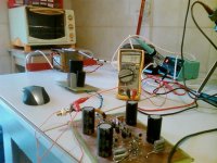
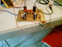
i connected the ground of the in/out connectors together and the ground that goes to the board is only sourced from the input...and so the signal ground goes only once and in one place to the main ground plane.
This time i try to change/rise the gain resistor (now set up to 240ohm) and see if i get the same result....
Please any suggestion on how to get rid of these problems is very welcome.
I was thinking if it could be caused by the fact that i'm not using a ztx450/550 or a 100hfe transistor.
thanks for all the attention and advice.
Attachments
Stefanoo said:main parameters now:
connecting a multimeter together i get an output DC of 0.4mV (very good!) and ....that could already been seen on the scope...but to have a confirm of the result...it says a 3mV AC.....(i guess it is bad!)
Just a few thoughts:
The multimeter measurements are completely meaningless - the "very good" 0.4mV is taken after a cap so it should be zero anyway. The 3mV AC doesn't mean much as we don't know how high your multimeter goes. Not nice anyway.
Obviously you have oscillations. It is easier to advise what doesn't make sense doing.
- do not touch the gain
- do not replace the bipolar transistors. Having different Hfe will have some effect upon the dc conditions. I think you previously mentioned that your dc op-points were all fine.
What to do:
- raise all gate stoppers to 1k. The fact that you're using it single ended is irrelevant
It is not clear how you performed the scope measurements. Were the inputs grounded? Did grounding them have an effect upon the oscillations?
ok.
I troubleshooted for awhile the circuit.
I have had found one problem so far: i had a cold joint on the input capacitor of the negative side.
That's good....fixed it.
But....as i outlined at the beginning ..... i have problems with the scope.
I had the oscilloscope hooked at the output by crocoldiles.
so when i unplugged the power supply i have noticed that that wave that i have posted stayed on the screen and so i started wondering what it could be wrong.
Now for example....if i set the vold/div scale at 5mV and attach the probe to the circuit WITHOUT supply, i get that modulation of frequency.
At this point...i guess that the scope is unusable ...at least if i need to measure low noise or check for little problems.
I'll start looking for another scope, i guess it is a must at this point.
anyways....i connected the pre to my system and this time it sounded better than the last time (that cold joint was causing some distortion at the output).
I don't have any hum on the woofer but i just hear a little hiss....liittlee hiss on the tweeter.
Could it be caused by a low value of gate stopper resistor?
I'll try to rise them up as you suggested and see.
Any other advice to fix this hiss?
Could it be a wrong ground wiring?
This time i have build my own power supply.
i have Jointed the ground wires all to one point and it seems to work.
I don't think the psu is injecting that hiss since i had it (even louder) using the power supply of my integrated amplifier.
I'm not quite clear as to why you're convinced that your oscilloscope is having problems. A naked probe is quite capable of picking up 50/60Hz fields from the air. Ground the probe connection and see if it goes to a straight line.
Also, you might want to keep in mind that a x10 probe doesn't multiply the incoming signal by a factor of ten, it divides it by ten so you can look at a signal 10x larger than you would otherwise be able to see.
Grey
Also, you might want to keep in mind that a x10 probe doesn't multiply the incoming signal by a factor of ten, it divides it by ten so you can look at a signal 10x larger than you would otherwise be able to see.
Grey
hi grey,
yes my scope has a power supply related problem.
A 10x probe divides the signal per 10...i knew that already; so if i have a 10V in signal the scope will read 1V.
My question is: how can i measure if the pre is working well and therefore has a noise around 5uV, if the scope has a maximum resolution of 5mV per div ...which is 1000 times bigger than that value ...and more with a 10x probe..?
If i ground the input (there is a switch to ground) the trace goes flat sometimes and some other times not.
Well....i don't have clue of why i get that modulation when i switch to 5mV....but i don't think is normal.
i'm using a P6105 tek probe, i don't think it is not suppose to get anything since it should be shielded, am i wrong?
Could it be the probe damaged?
I actually have two of them...and i get the same exact thing on both...
so i found out what it was wrong.
You were right grey, it was the probe.
I think i have defective probes....since i get a weired noise.
I tried to connect a short bnc to the scope.
That distortion disappeared completely.
So if i have to analyze low noise signal i would need a good 1Xprobe.
Is this correct?
Should i be looking for a good 1X probe?
One of us isn't understanding the other--it's probably me. Amongst other things, I'm not sure I understand what you mean when you say that you are getting a weird noise when you use the probe...surely you don't mean to say you have the circuit hooked up to your audio system when you're trying to test it...do you? If so, all I can say is that this is most unwise.
I also have to say that I have some sympathy with earlier posts asking you to take more time thinking things through instead of asking others to do your thinking for you.
There are too many uncontrolled variables involved in this for others to be able to be of much help to you in solving problems over the Internet, even with the best of intentions. I, speaking only for myself, try to avoid getting too deeply involved with "fix-it" threads. Others delight in solving diagnostic/repair problems--it's just me.
This thread began as a preamp comparison. At least that was what I thought, based on the title and first post or two. Then it turned out that there were tantalum caps, then that the circuit might be oscillating, then that the oscilloscope might be bad, then it began to look as though the probe was at fault...and so on...
My suggestion at this point is to stop, sit down, and think. Only think. Do nothing but think. Develop a plan--a reasonable, consistent, logical plan--for attacking this/these problem/s. I understand that you're impatient to listen to things, so am I for that matter, but you're not going to get where you want to go if you continue doing what you're doing. No one can do everything for you. At some point you will have to take action on your own behalf.
The situation--as I understand it (subject to the possibility that I've completely lost sight of what's going on)--leads me to make the following suggestions:
--Get your scope situation under control. If it's the probe, keep in mind that a probe can be as simple as a piece of flexible coax with the hot lead exposed. If it's the power supply, have the scope serviced or try to find another.
--Check all other instruments that you may have on hand to assure that they are functioning.
--Sit and think. Then think some more. For example: As an earlier poster pointed out, measuring the DC after a DC blocking cap isn't really all that meaningful of an activity. Unless you have reason to believe that the cap is defective, it's not a measurement that's worth reporting. Think about the function of a DC blocking cap.
--Check your circuits for bad solder joints. Check the orientation of active devices and polarity-sensitive caps. Turn it on--with a Variac, if possible. Check DC operating voltages. Apply a signal and check AC operating voltages.
--Stop and think some more.
--Recheck the circuit.
--Stop and think some more.
--Then and only then is it reasonable to hook the circuit to your system.
--Evaluate the sound.
--Consider your parts choices. Are they reasonable? Are tantalum caps a good choice? You do not have to go as far as the high-priced boutique parts to get decent performance.
--Before attempting to compare circuits, consider whether the parts quality in the two circuits are more-or-less equivalent. If one has ultra-high quality parts and the other has junk, it's not a fair comparison, no matter what topology is being used.
I don't doubt your enthusiasm, and I certainly don't want you to lose that enthusiasm, but I sometimes get the feeling that you're trying to run before you can walk. A little more considered approach might be just the thing. You've started an awful lot of threads over some really mundane things. People have suggested in many of those threads that you take a little more responsibility on your end. Some were rather rude about it, others were nicer, but you don't seem to have gotten the message from any of them, regardless of how they said it.
I will now bow out and let others who are more excited by fix-it threads to take over.
Grey
P.S.: If you don't already own a good electronics text, I'd suggest buying one.
GRollins said:P.S.: If you don't already own a good electronics text, I'd suggest buying one. [/B]
Which one would suggest?
Manu
Great suggestions Grey. If i may add just a couple of comments.
- "sit down and think" does not necessarily mean "start a new thread".
Many answers can be gathered the old fashioned way from books, reading, thinking and searching. There is a lot to be gained from this more time-consuming method.
- the easiest way to get something working reasonably well is to show less creativity and follow a tested design and construction method. This means no home-designed PCBs, no frivolous substitutions of components. At least until you have several working and hopefully good-sounding projects behind you.
Once a pcb from a "group buy", or at least one duplicating a tested layout, is populated and works well you can always go wild with components, power supplies and other "audiophilia".
Maybe time for some New Year resolutions? 🙂
Horowitz & Hill...the same one recommended in every What-Book-Do-I-Buy thread on the site (ample proof, as if any were needed, that people don't use the search function before starting a new thread). I specifically do not recommend Self or Sloane unless you are firmly convinced that feedback is the cure to all problems and have no intention of changing your mind...ever.
Grey
Grey
GRollins said:Horowitz & Hill...the same one recommended in every What-Book-Do-I-Buy thread on the site (ample proof, as if any were needed, that people don't use the search function before starting a new thread). I specifically do not recommend Self or Sloane unless you are firmly convinced that feedback is the cure to all problems and have no intention of changing your mind...ever.
Grey
perfect, i'll try to get this book ( i think you are referring to the "Art of Electronic") since i already have self..and personally i do not agree with feedback and class B amp...and that is what it all talks about.
GRollins said:One of us isn't understanding the other--it's probably me. Amongst other things, I'm not sure I understand what you mean when you say that you are getting a weird noise when you use the probe...surely you don't mean to say you have the circuit hooked up to your audio system when you're trying to test it...do you? If so, all I can say is that this is most unwise.
I also have to say that I have some sympathy with earlier posts asking you to take more time thinking things through instead of asking others to do your thinking for you.
There are too many uncontrolled variables involved in this for others to be able to be of much help to you in solving problems over the Internet, even with the best of intentions. I, speaking only for myself, try to avoid getting too deeply involved with "fix-it" threads. Others delight in solving diagnostic/repair problems--it's just me.
This thread began as a preamp comparison. At least that was what I thought, based on the title and first post or two. Then it turned out that there were tantalum caps, then that the circuit might be oscillating, then that the oscilloscope might be bad, then it began to look as though the probe was at fault...and so on...
My suggestion at this point is to stop, sit down, and think. Only think. Do nothing but think. Develop a plan--a reasonable, consistent, logical plan--for attacking this/these problem/s. I understand that you're impatient to listen to things, so am I for that matter, but you're not going to get where you want to go if you continue doing what you're doing. No one can do everything for you. At some point you will have to take action on your own behalf.
The situation--as I understand it (subject to the possibility that I've completely lost sight of what's going on)--leads me to make the following suggestions:
--Get your scope situation under control. If it's the probe, keep in mind that a probe can be as simple as a piece of flexible coax with the hot lead exposed. If it's the power supply, have the scope serviced or try to find another.
--Check all other instruments that you may have on hand to assure that they are functioning.
--Sit and think. Then think some more. For example: As an earlier poster pointed out, measuring the DC after a DC blocking cap isn't really all that meaningful of an activity. Unless you have reason to believe that the cap is defective, it's not a measurement that's worth reporting. Think about the function of a DC blocking cap.
--Check your circuits for bad solder joints. Check the orientation of active devices and polarity-sensitive caps. Turn it on--with a Variac, if possible. Check DC operating voltages. Apply a signal and check AC operating voltages.
--Stop and think some more.
--Recheck the circuit.
--Stop and think some more.
--Then and only then is it reasonable to hook the circuit to your system.
--Evaluate the sound.
--Consider your parts choices. Are they reasonable? Are tantalum caps a good choice? You do not have to go as far as the high-priced boutique parts to get decent performance.
--Before attempting to compare circuits, consider whether the parts quality in the two circuits are more-or-less equivalent. If one has ultra-high quality parts and the other has junk, it's not a fair comparison, no matter what topology is being used.
I don't doubt your enthusiasm, and I certainly don't want you to lose that enthusiasm, but I sometimes get the feeling that you're trying to run before you can walk. A little more considered approach might be just the thing. You've started an awful lot of threads over some really mundane things. People have suggested in many of those threads that you take a little more responsibility on your end. Some were rather rude about it, others were nicer, but you don't seem to have gotten the message from any of them, regardless of how they said it.
I will now bow out and let others who are more excited by fix-it threads to take over.
Grey
P.S.: If you don't already own a good electronics text, I'd suggest buying one.
Well i first want to thank you for the big long answer.
Said that, now i want to outline just a couple of things without getting to dispersive.
1- the circuit is working fine and therefore i thankfully not have to check diodes..transistors...value...and so on
2- i evaluate the sound of the preamplifier just at the beginning, but then i decide to follow the suggestion received here and stop listening to it and check the proper function of the circuit itself. Therefore on the test bench i only have the circuit and the psu...and no....i am not so impatient to listen to it...even if it is, of course, the best part...but before to do so i want to make sure that is working as it's supposed to.
Stated the things above...the only thing i was wondering...and that was the reason of the last post and the email i have sent you.....was:
How is it possible to make LOW value voltage measurements(5mv/div)...with a simple piece of wire or as called 1X probe, without being covered form fuzzy noise on the screen.
That is what i have been trying to do in the last couple of days...trying to shield the probe and so on....but i don't understand how i can get noise (like 8-9mVpk-pk) on the screen just touching the board that is not powered.
Since i had connected it to the system got no hum on the woofer but just a little noise (hiss) on the tweeter, my purpose on doing that was to visualize on the scope this noise to get the control of it.
I don't know if it is the scope and tomorrow hopefully i' ll go to a laboratory of a friend of mine and use the teck TDS210 to get a better handle....
My feeling and my only two cents are for some on the probe on the arrangement or something that i don't get because...when i ground the input of the scope, the trace goes straight no matter what vold/div scale is selected.
I don't know but my way of thinking leads me to think that if it was the scope grounding the input wouldn't have effect on the noise i see on the crt...but i might be wrong.
.... how can you measure for example if the power supply has less then 5mV ripple....or even worse....if the preamplifier has 5uV noise?
Do you guys use a particular probe...a partuclar arrangement.....any advice? that's all...
wayne325 said:
Agreed.
What I wanted to point out is that the world already knows what
X is - since Nelson told us all what it is in the patent.
Hi Wayne,
per se a patent is public. That said every skilled engineer is able to design a working circuit according to that published patent. He even is free to do that for his private use! Whats illegal is to make business with such a circuit in the country where the patent is valid.
Sometimes I think that part of the diya community just wants to copy an existing design instead of reading patents and whitepapers to gain knowledge and make their own things and tinker around with them.
IMO it makes far more fun to experiment and sometimes be successful than just copy and listen.
Uli

Stefanoo said:
.... how can you measure for example if the power supply has less then 5mV ripple....or even worse....if the preamplifier has 5uV noise?
Do you guys use a particular probe...a partuclar arrangement.....any advice? that's all...
The easy and cheap solution is to build a preamp using low noise opamps. It will be bandwidth limited but sufficient for audio measurements. Plus you can use it with your sound card as well.
Hi Stefanoo,
Regarding the signal you see on your scope. I think it would be most helpfull if you could draw a schematic or block diagram of all the connections in your test and measuring setup.
I always have such a signal trace on my scope until i connect the grounds between the circuit and the scope correctly. And besides of that, choosing the ground point for your signal measurement will also have an influence.
If you could provide a diagram the pro's here might help you out.
regards
Joris
analog_sa said:
The easy and cheap solution is to build a preamp using low noise opamps. It will be bandwidth limited but sufficient for audio measurements. Plus you can use it with your sound card as well.
yes,
that is what i was thinking of.
I actually got from a friend of mine a BB INA118P...but it seems to be specifically for signal around 10Hz .
In the meantime i decided to follow your suggestion and build someone else's layout (Veteran) adjusting it for my footprints.
after this re-make.
I have notice, though, using the TDS210 of this frien of mine ...at 2mV/div that if i just blow a little bit of air on the mosfets i can see a thermal derive.
And more....if i touch the mosfet's case they seem to act as an "antenna".
I tried as you suggested to rise the gate stop resistor up to 1Kohm....but it didn't change this fact.
As soon as i will be print and try out this lay out i will post the results and then i would like to build this little front end to step up the volt div at least to be able to say 100uV...or so.
If you have in mind some specific circuit that i can look at please let me know.
jazz said:Hi Stefanoo,
Regarding the signal you see on your scope. I think it would be most helpfull if you could draw a schematic or block diagram of all the connections in your test and measuring setup.
I always have such a signal trace on my scope until i connect the grounds between the circuit and the scope correctly. And besides of that, choosing the ground point for your signal measurement will also have an influence.
If you could provide a diagram the pro's here might help you out.
regards
Joris
I had soldered in the bnc cable to the output of the preamplifier.
I had to soldered it in because if i would try to have a little crocodile with a short wire i would p[ick up noise and i wasn't able to make any measurements.
Ground, therefore, was taken at the output of the preamplifier circuit and would go to the cold pole of the probe....i didn't have any particular arrangement....
In this way i was able......adjusting the cable making sure that wasn't capturing external field....to have a flat trace when circuit was off...and therefore to see at 5mv/div 1mv of noise at the output (pretty bad though!)
But....if i would try to disconnect the power supply from the circuit and hook the positive to the hot pole of the probe and the output ground of the power supply to the ground of the BNC cable i would see a very fuzzy trace even without power and in this way i wouldn't have been able to see any noise on the power supply itself.
I don't know....do you usually follow a specific rule when connecting the probe for this low voltage level measurements?
What way do you arrange your ground in for this measurements?
Hi Stefano
The only worrying bit is that the mosfets "act as antenna" when you touch them. This sounds too much like oscillation. Just tried touching mine and the output trace is completely steady.
I wouldn't worry too much about the noise/hum you see at output. Don't know what output attenuator you use but without one there is about 4k8 between the scope probes with some amount of pcb traces on either end. Apart from the thermal noise, which is negligible, this resistor and the output wiring acts as an antenna and picks up all sorts of stray fields. If your circuit is not inside a well screened case you would expect some 50Hz/RF pickup.
As an experiment hook your probe across a similar value resistor and see how it looks on the scope.
- Status
- Not open for further replies.
- Home
- Amplifiers
- Pass Labs
- preamplifier Pass X2.0/1