Tom (neurochrome.com) uses electrolytic caps( nichicon es) as coupling caps in one of his amps( modulus 686) . The distortions of this amp are ridiculous low.
About your preamp, I would ignore c28-29 , they sit right before the coupling caps from the power amp.....
And I think I would ignore the whole balance group, including c21-22...
About your preamp, I would ignore c28-29 , they sit right before the coupling caps from the power amp.....
And I think I would ignore the whole balance group, including c21-22...
Tom (neurochrome.com) uses electrolytic caps( nichicon es) as coupling caps in one of his amps( modulus 686) . The distortions of this amp are ridiculous low.
About your preamp, I would ignore c28-29 , they sit right before the coupling caps from the power amp.....
And I think I would ignore the whole balance group, including c21-22...
Thanks for the good points. My current source of caps doesn't run the nichion, so will probably go for the polyester type for economy and ease of sourcing. I may just get rid of c28-29 as you suggest.
I didn't want the balance pots either but my living room/ speaker arrangement means I'm not dead in the middle of the speakers hence the need.
I could probably do away with the entire subwoofer section as well, as I don't have or intend to use a subwoofer. I could then separate P3A and P3B into individual pots and use them for the balance that I need. It would also make the PCB simpler.
Assuming I did remove the subwoofer section. What do I do with the bottom ends of R25 and 26?
Last edited:
if you want not to include the subwoofer section you have to ignore r25-26 completely , but to be honest I would keep that option , you could do a small daughter pcb just for subwoofer .
As for measurable distortion, electrolytics do increase distortion compared to film capacitors. The electrolyte is nonlinear and capacitance changes based on the voltage across the cap, which introduces distortion as the signal level increases. They also have higher ESR than film caps. Using a good low-ESR film cap in parallel will deal with any ESR related nonlinearity.
But distortion is greatest at low frequencies, where higher reactance means more voltage is developed across the cap. It is good practice to use oversize values to push the cutoff frequency as low as practical in the circuit. This is because the distortion increase begins well above the cutoff frequency. Use of nonpolarized electrolytic caps, which internally are two polarized caps of opposing polarity in series, will also lower distortion. Each internal cap sees half the voltage, and the total distortion is reduced. Two separate polarized caps could also be used in series to achieve this.
But distortion is greatest at low frequencies, where higher reactance means more voltage is developed across the cap. It is good practice to use oversize values to push the cutoff frequency as low as practical in the circuit. This is because the distortion increase begins well above the cutoff frequency. Use of nonpolarized electrolytic caps, which internally are two polarized caps of opposing polarity in series, will also lower distortion. Each internal cap sees half the voltage, and the total distortion is reduced. Two separate polarized caps could also be used in series to achieve this.
No. Not unless the 'bypass' cap has such a high value than it can do the coupling job without the electrolytic in parallel. There is no engineering reason to 'bypass' an audio coupling capacitor.stevebogus said:Using a good low-ESR film cap in parallel will deal with any ESR related nonlinearity.
No need to use bipolar caps. Just use a bigger value.
No need!!! Those bright green, Nichicon Muse ES capacitors look so good that you would be crazy to use anything else when higher values are required. 47uF, 100uF and 220uF will work for most jobs.
Take a look at this : Nichicon Muse ES bipolar caps measured: <-120dB THD, <-140dB IMD
Don't be afraid to use those nichicon es !
Don't be afraid to use those nichicon es !
I am old fashioned. Direct coupled and balanced circuitry is all I use for sources. No coupling caps.
Using an input transformer on the input of a My_Ref FE. Does the balanced to single ended conversion and dc blocking. They are a little more expensive than electrolytic. Maybe cheaper than using film caps.
Using an input transformer on the input of a My_Ref FE. Does the balanced to single ended conversion and dc blocking. They are a little more expensive than electrolytic. Maybe cheaper than using film caps.
if you want not to include the subwoofer section you have to ignore r25-26 completely , but to be honest I would keep that option , you could do a small daughter pcb just for subwoofer .
Ok great, I'll remove r25-26.
I've done layouts for both options but will probably go for the one without the subwoofer, as I've got nowhere to put another speaker.
An input transformer might have only limited DC blocking capability before saturation sets in and causes bass loss.
Take a look at this : Nichicon Muse ES bipolar caps measured: <-120dB THD, <-140dB IMD
Don't be afraid to use those nichicon es !
Hmmm!!! Mouser Mexico have them 25 for $0.771 each Cheap as chips! $0.593 in the US. So much for not being able to source locally. Changes things somewhat.
https://www.mouser.mx/ProductDetail...E8mTj7sTGqg==&countrycode=US¤cycode=USD
I've also realised they have a smaller footprint than the 4.7uF polyester I was planning to use.
I may go this route after all🙄
So, the muse is a Bi-Polar/Non-Polar cap but appears to have a long and short lead.
Is there an orientation regarding the leads? This article using muse UES1H010MDM would appear to indicate that there is! TDA7297 Build Guide
Quote from the article "Install the upside C1 and C2 capacitors, 1uf Nichicon Muse. Long leads go toward the input (as circled)"
Is there an orientation regarding the leads? This article using muse UES1H010MDM would appear to indicate that there is! TDA7297 Build Guide
Quote from the article "Install the upside C1 and C2 capacitors, 1uf Nichicon Muse. Long leads go toward the input (as circled)"
Last edited:
And it adds distortion as wellAn input transformer might have only limited DC blocking capability before saturation sets in and causes bass loss.
Mexmike, about orientation of an nonpolar capacitor or resistor or plastic capacitor....some people believe they could hear the difference. It might be a difference but I can’t hear it.
Mexmike, about orientation of an nonpolar capacitor or resistor or plastic capacitor....some people believe they could hear the difference. It might be a difference but I can’t hear it.
Nice. I've decided to go ahead and use the Nichicons after all. Good enough for Tom, good enough for me🙂
I'll orientate them all in the same way relative to the schematic, assuming that is that they come with different length legs. I will probably follow the advice given in TDA7297 Build Guide "Long leads go toward the input"
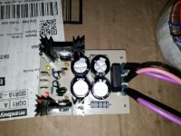
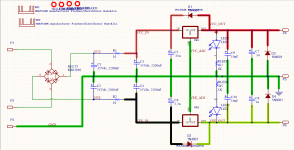
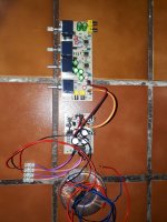
15V dual rail power supply for the Cordell SGC/ SC200 Preamp, done and tested OK so far, with 150mA load. The board measures 85x56mm.
I'd thought about using the LM317/337 combo but settled on the LM7815 LM7915 regs and a CRC (2k2-10R-2k2) filter prior to the regs for simplicity. If it proves noisy, I'll remake with the LM317/337.
The regs have SK104 Heatsinks. The KBU1010 rectifier is over the top but its a used one and all that I had.
There are a couple of LEDs on the output rails that consume almost 4mA each. I've come to realise that using LEDs at their rated current is way to bright for my needs. I just want to see a glow, hence the 3k7 resistors!
The small caps before and after the regs are IAW figure 16. split power supply of the LM78XX Fairchild ON datasheet, so hopefully I shouldn't get into trouble by not using 100nF all round. All but the 100nF are tantalum.
With no load, the DC input to the regs is 21.8V which might be slightly high. I could also use the other tranny winding which gives 1V AC less than the current winding.
The bottom copper pdf is for toner transfer. Use at tour own risk!
Attachments

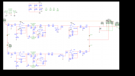
This is the version of the preamp I will most likely go for, without the sub woofer section. I couldn't find a proper Alps balance pot, so used two individual pots for LR level control. As previously mentioned, I found the Nichiocon UES1V101MPM1TD 100uF caps and will use them after all.
I may still make a couple of changes to the PCB prior to build but hopefully it'll work.
Any comments and input always welcome.
Use the pdf for toner transfer at your own risk.
For the original design with sub woofer section, all credit to Jozef Grolmus and Jacob. The design can be found at…
diysmps
Nymeria (site appears to be down)
Attachments
Some minor changes made to hopefully improve the layout.
-Probably the most important! Decoupling caps moved nearer to the IC's
-RCA Audio out connectors moved inboard to allow for a narrower chassis using right angled pre-made/ purchased connectors
-Pots arranged slightly more symmetrically
-RCA pads a little bigger
-Thin edge traces at front and back of board widened as they were a little fragile after toner transfer.
-Slightly more copper left on the board with only one island
This will be the test PCB for assembly this weekend. I really hope the pots are wired in the correct sense and I haven't cocked up anything too seriously 😱
Any and all comments more than welcome
Attachments
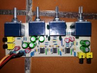
This Thing Rocks!!!
Assembled and tested the pre amp PCB today.
I fitted all the Nichiocon UES1V101MPM1TD 100uF caps with the long leg towards the previous output section. I'm not sure if it makes the slightest bit of difference. It was a little tight behind a couple of the pots, so I might move a few of the caps by about 1mm on my next PCB. I'll post an updated PDF with the modifications shortly.
I didn't want to risk blowing up my Cordell, so I tested the pre amp first with various frequency signal inputs going from 16Hz to 20Khz at 200mV and viewed the output on my scope. I also used TLO72's for the test as I didn't want to risk my OPA2134's or the LM4562NA's which I also want to try later. Everything went well so I went for it with my Cordell SGC and with surprising results!
This thing is a monster!!! Way way better than I could have imagined. The range of tone control is vast to the point I thought I might break something. It completely blows away the commercial pre amps I bought from Iwistao.
Now all I need is to find a decent chassis with no holes in the front
Youtube video of the result YouTube You can hear the missus clattering about in the kitchen in the background ha ha ha.
Attachments
Last edited:
Assembled and tested the pre amp PCB today.
I might move a few of the caps by about 1mm on my next PCB. I'll post an updated PDF with the modifications shortly.
Moved some caps around to give clearance at the pots and some general tiding up.
Attachments
- Status
- Not open for further replies.
- Home
- Amplifiers
- Chip Amps
- Preamplifier For Cordell Super Gainclone and SC200