Do you mean that there is only 42V from the 6DJ8 Plate to the 6DJ8 Cathode?
390V - 42V = 348V
The resistance from the Cathode to ground:
33k + 2.7k = 35.7k
348V / 35.7k = 9.7mA
With the Grid -1.7V versus the Cathode, how does that look on the 6DJ8 curves?
That does not look correct on the 6DJ8 curves I looked at.
Having the 6DJ8 Cathode at 348V, and the filament at 160V does not work either, it is 188V cathode to filament,
the tube is in violation of its maximum cathode to filament spec.
At least a couple of things are incorrect.
Last edited:
the only way to make the voltages same like in the schematic is:
1. removing the R1 2k7
2. increase the resistance R13 to 43k
and only on one triode.
1. removing the R1 2k7
2. increase the resistance R13 to 43k
and only on one triode.
Replace the tube ... maybe you did something wrong or the quality wasn't good . Was NOS or produced now ? The voltages are high but I don't think a good ECC88 would fail so easily .
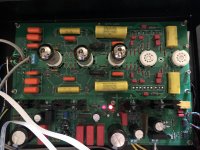
It worked before you put it in the case.
Could a wire or solder connection have opened?
Could a tube socket have been spread and no longer contacting a tube pin?
Could a wire, pin, or other connection been made to ground, to B+, to the adjacent circuit, etc.
The preamp might no longer be the circuit that it was when it worked out of the case.
I see no volume control !
Of course, it can't work with the input left open. it is part of the feedback! I tested it with open and this upset the circuitry.
Needs improvement!
The circuit is working now however it will need some improvement. I use it with solid state power amp, 47k input impedance.When the amp is on first and this preamp turns on, after 40 seconds the muting relay releases and gives an output to the amp. I can hear "thump" through the speaker and also upsets the speaker protection in the amp.
Turning of the preamp first is also no good.
Also, the TONE Defeat switch (driven by relay). At the beginning within first 10 minutes, switching this ON and OFF makes loud thump in the speakers. It gets better after the preamp is warmed but does not eliminate the thumps, they are just less audible.
Any suggestion would be much approciated!
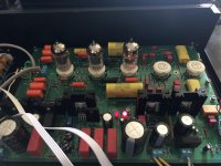
Attachments
And where are those muting relays in your circuit ?
Anyway the output should have a clear current path to ground , a loading resistor 500K aprox , so the output capacitors will be normally charged by the time the amplifier is connected .
Anyway the output should have a clear current path to ground , a loading resistor 500K aprox , so the output capacitors will be normally charged by the time the amplifier is connected .
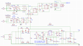
I don't like that the OUT after the capacitor is wired to go back in the circuit ... maybe some DC voltage can appear there , do some measurements .
If this is the case you can add a second capacitor just for coupling the output .
And add some output resistance as I said in previous post .
If this is the case you can add a second capacitor just for coupling the output .
And add some output resistance as I said in previous post .
it seems i have DC voltage at the beginning the circuit powers up and is there until stabilises.
Last edited:
Where exactly in the circuit is this DC voltage during power-up?
Do you mean C29, 1uF?
If you mean at the output, the cathode voltage goes up, and the series coupling capacitor, C29 charges up, and that causes a voltage at the output, until the time that the cathode is at its final quiescent voltage, and until the cap is fully charged to that voltage.
Then, at that time, the quiescent voltage at the output better be zero.
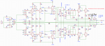
And that raises the question, where is there a resistor that connects to ground, that the other end of the resistor connects to the output of C29?
It is missing in the schematic.
If your DC meter is the only DC path from C29 to ground, then you need to add a resistor there to ground.
Prevent you power amp from having to "swallow" all of C29's charging current.
Do you mean C29, 1uF?
If you mean at the output, the cathode voltage goes up, and the series coupling capacitor, C29 charges up, and that causes a voltage at the output, until the time that the cathode is at its final quiescent voltage, and until the cap is fully charged to that voltage.
Then, at that time, the quiescent voltage at the output better be zero.
And that raises the question, where is there a resistor that connects to ground, that the other end of the resistor connects to the output of C29?
It is missing in the schematic.
If your DC meter is the only DC path from C29 to ground, then you need to add a resistor there to ground.
Prevent you power amp from having to "swallow" all of C29's charging current.
Last edited:
at the output. depends on position of the TONE switch. Measured with DC meter through 1k resistor.
1. Sw shorted at 3 & 1 (1 & 3 bottom channel), measured at the output. after the power up I could see 2.5VDC then it goes down to +40mV and -40mV never stabilise on both channels
2. SW shorted at 3 & 2 (1 & 2 top channel) same as a above but after a while channels stay at 0mV.
the 100k load resistor is fitted 1 and the second channel 3 of this tone switch to GND
Last edited:
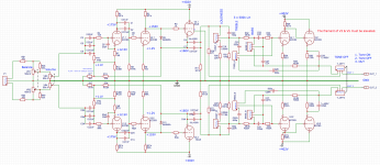
You not only have a 1uF cap from the output of the last stage cathode follower, and any leakage of that cap,
But you also have a 10uF cap from the previous stage cathode follower, the 6DJ8, that is at +160V.
Are either of those Electrolytic caps?
Leakage = DC.
And, even if they are not electrolytic caps, and even if they are not leaky, then . . .
Time varying current or voltage in cathode followers gives time varying voltage output from the coupling caps that connect to the cathodes.
Time varying output of a preamp can be caused by Power Mains voltage changes (either B+ or filament voltages changing, or both), and by tubes that warm up slowly and drift over time (perhaps including ambient air temperature shift).
Yes, you have regulated supplies, but what kind of drift do they have, including time, and ambient air temperature changes?
I have seen DC balance of triodes that used a variable filament supply on one tube, to get the plate currents to match.
And there is lots of 'inertia' to using that method.
A rule of thumb says the complexity of a circuit goes up according the square of the number of parts in a circuit.
And the difficulty of troubleshooting also goes up by the square of the number of parts.
The difficulty of analyzing a circuit increases by the number of connectors in the schematic that do not have the parts drawn in.
Switches, pots, etc.
I did not even see that 10uF path from the 6DJ8, and did not know all its paths and resistances (the connections to parts, and part values are not shown).
Clarifying a schematic by only showing pin numbers, not the parts and values that are connected to them complicates the analysis.
The tube that drives the 6DJ8 is DC coupled to the 6DJ8. That means that a high gain tube, which may be subject to DC drift, will be driving a cathode follower, that drives a very long time constant 10uF cap.
It seems you have your work cut out for you to troubleshoot all the possibilities.
Last edited:
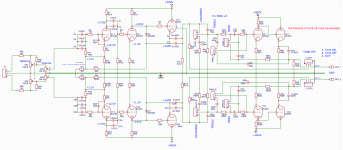
I am thinking on giving up the entire tone control section... no one use it these days, its all passive anyway.
The tone control circuits have loss (all those parts attenuate the signal).
Giving the tone control up, is OK for lots of people.
I believe you also have to take out one gain stage, or now you have too much gain.
Too much gain amplifies the hum, and amplifies the noise of the input stage.
The gain stage that made up for the tone control attenuation needs to come out when you remove the tone control parts.
Most likely, you could do a good job with only 2 gain stages, and 1 cathode follower.
For even lower gain that is all that some stereo systems need, 1 gain stage and 1 cathode follower is all that is needed.
Just my opinion.
Last edited:
Thanks for participating in the project. I will remove the tone control circuitry and do proper measurements later on to have some idea of the performance.
R1 2k7 resistor is to reduce the gain by 10dB if it is removed which I have this now. I did some measurements some time ago where SNR was around 90dB and the frequency response was really nice. That was when the PCB was not in the enclosure.
I am listening it now and is not bad...
R1 2k7 resistor is to reduce the gain by 10dB if it is removed which I have this now. I did some measurements some time ago where SNR was around 90dB and the frequency response was really nice. That was when the PCB was not in the enclosure.
I am listening it now and is not bad...
Attachments
Add a second capacitor from cathode to out , cut the original trace but the old circuit will still work the same for negative feedback . The tome control circuit is active , thats why needs signal back from the output capacitor
Attachments
Last edited:
thanks mate for the advise, i think it would work just fine. Anyway, I have already decided to turn off the tone control circuit. I ended up having some issues with pots, they are brand new but already have experienced problems with cracking noise, I would have to buy another set and probably ALPS. these were BOURNS - no good!
Besides, i noticed the tone control circuit slightly overloaded previous stage. I didn't fix that.
now. Ive been playing after modification and it sounds great, really! I've swapped ECC83 with 5751, a bit lower gain but is good so far. I will swap JJ E88CC with Electro-harmonics next week.
Besides, i noticed the tone control circuit slightly overloaded previous stage. I didn't fix that.
now. Ive been playing after modification and it sounds great, really! I've swapped ECC83 with 5751, a bit lower gain but is good so far. I will swap JJ E88CC with Electro-harmonics next week.
Last edited:
- Home
- Amplifiers
- Tubes / Valves
- Preamplifier - 6DJ8 BIAS