Ok, after a week of searching and reading, following the suggestions made by forum members on various posts, I decided to make a passive preamp for my quad 405 (linestage only). Having said that, since I will build a tube preamp for my phono stage in any case, I'm thinking, let's add the possibility to switch from passive to tube buffer in the preamp for the linestage.
I have found a few possibly suitable tubes in my stuff (salvaged mostly): 2 x 6922(unused!), 2 x 6cg7 and 2 x 12ax7. I also have old preamp boards, unpopulated, that I would like to use, even if I leave a few areas unpopulated on them. The schematic is as follows, and I was thinking of having the first stage with V1 left blank and using only the second stage (cathode follower) for buffer purposes. Since both channels are using the same tube, where do I connect the B+ on that schematic? Also, what do I do with r6 r16 r18 (what is their use)?
I am tube newb, so a few things are still unclear to me... please assume I am 5 years old when you explain something to me 😉 (I'm afraid I'm good with numbers, but not all the technical terms as of yet...)
Thanks
Attachments

Where did you get that circuit? It has two identical amps, one per channel, but with lopsided B+ arrangements. It is not surprising that you are confused. The B+ supply should probably be attached to the middle of R16, so that each channel sees the same voltage.
As a first step I would be tempted to split R16 in two as you suggest and decouple the left and right ends of it and also repeat the left channel first stage PSU decoupling on the right channel first stage.
Cheers
Ian
Cheers
Ian
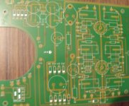
It is a preamp board I had in my random stuff pile, it looks like the picture attached. Sorry for the crappy quality, I was in a hurry, I'll take a better one if needed. I have two btw, so I can experiment on one. The circuit is quite visible, I'd like to remove the part under the toroid hole, cause I have two transfos, one for hv, one for lv.
Splitting r16 is feasible, what about c6 and r4?
Thanks.
Splitting r16 is feasible, what about c6 and r4?
Thanks.
Attachments
Last edited:
Difficult to comment on mods to the PCB without a better picture. I can't read the the component legend.
Cheers
Ian
Cheers
Ian
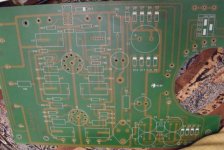
That's a much better picture. Looking at the (single sided) layout I would guess that R6, R16 and R18 are meant to be zero ohm links.
Q2 is part of a simple regulator. D9 thru D12 are what I would guess are four zener diodes in series and Q2 is the series pass transistor.
Cheers
Ian
Q2 is part of a simple regulator. D9 thru D12 are what I would guess are four zener diodes in series and Q2 is the series pass transistor.
Cheers
Ian
You, sir, are making a lot of sense... the schematic looks way nicer that way. I thought I was missing something, and there it is, it's single sided!
Is the idea of bypassing the gain stage a good one? or is there another way of achieving unity gain apart from using only the cathode follower?
What are c6 and r4? Is there a name for such an arrangement?
Thanks
John
Is the idea of bypassing the gain stage a good one? or is there another way of achieving unity gain apart from using only the cathode follower?
What are c6 and r4? Is there a name for such an arrangement?
Thanks
John
C6 is a decoupler. It reduces noise and hum on the HT (B+) supply, and also reduces unwanted coupling between different stages.
R4 will simply use up current. It may be that it was originally part of an HT dropper arrangement.
The only other way to get unity gain is to use an anode/plate follower. This will have a lower input impedance than a cathode follower, and possibly more noise. It wil invert the signal.
R4 will simply use up current. It may be that it was originally part of an HT dropper arrangement.
The only other way to get unity gain is to use an anode/plate follower. This will have a lower input impedance than a cathode follower, and possibly more noise. It wil invert the signal.
R4 will simply use up current. It may be that it was originally part of an HT dropper arrangement..
It is probably there to ensure the HT capacitors get discharged when the power is turned off.
Cheers
Ian
Alright then, since I'm aiming the 200v range B+, perhaps 3x51v zener and a diode would do the trick there. Is there a power transistor that is usually used in this type of circuit, or does any general use transistor work as well? Once the psu gets figured out, having solved the mystery or the weird resistors, I'll be able to start building this! yay
I'll bypass the gain stage as I originally thought, seems to make more sense.
Thanks, I know i'll have more questions though.
I'll bypass the gain stage as I originally thought, seems to make more sense.
Thanks, I know i'll have more questions though.
How does this look?
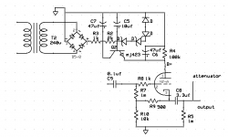
Ok, finally finished rethinking the whole thing, it looks like this. Part values ans selection was done with quick calculations and trying to match parts I already have on hand... Still, I can change them if I'm way off.
So, anything wrong with this? Should I consider something else?
thanks
Ok, finally finished rethinking the whole thing, it looks like this. Part values ans selection was done with quick calculations and trying to match parts I already have on hand... Still, I can change them if I'm way off.
So, anything wrong with this? Should I consider something else?
thanks
Attachments
So, anything wrong with this? Should I consider something else?
As a near unity gain buffer it looks fine but you lose the benefits of the low output impedance of the cathode follower if you put the attenuator after it.
Cheers
Ian
- Status
- Not open for further replies.
- Home
- Amplifiers
- Tubes / Valves
- Preamp with buffer design