I'd say great. Have a look here:
http://www.diyaudio.com/forums/pass-labs/146310-bf862-preamp.html
Hi
Your bf862 preamp are interesting, same topology than you B1 with gain, but I can't find any bf862 here arround. So I will stick to my 2SK170.
Thanx
Paul
Last edited:
I am short BC550 on this, Juma. Got ZtX parts and other fancy pants parts like TOshibas and Sanken bjt's. Only question is about Rs for ztx. It doesnt have same gain as BC, from what I see, but most is being used for feedback, so it should work ok, correct.
Found some LT SPice models, so will play around a little, but if you know good operating points or suggestions, I am all ears. Already have the boards etched for the BC550, but not big deal to switch.
You obviously know what "this" means, but I don't - this thread is full of different circuits. Please give exact schematic or post number, what parts you got exactly and so on... I'm still not clairvoyant 🙂I am short BC550 on this
I'm still not clairvoyant 🙂
You are getting closer with every post. 😀The circuit is in post 53. Comp Jfet feeding comp Bjt's. I don't have any bc550, so I substituted Ksa1381 and Ksc3503. Found numerous schematics with similar degeneration values for them so ill stick with what you posted. Should be done tonight. You know what I'm thinking

The value of R6/R7 can be lower (68R or so) because with 1381/3503 you can afford higher current through output BJTs. Ib will be higher too but it won't have much influence on input JFETs (they should run at Id of 5-7mA so loading them with about 100uA more is not a big deal).
Still, you got to have in mind that this preamp is made to drive light loads (F5) and the Zout is relatively high (about 1k or somewhat less).
All in all you'd be OK - work that pre and I go to practice my third eye, the original two are less and less useful each day... 😉
Still, you got to have in mind that this preamp is made to drive light loads (F5) and the Zout is relatively high (about 1k or somewhat less).
All in all you'd be OK - work that pre and I go to practice my third eye, the original two are less and less useful each day... 😉
... circuit is in post 53.
post 53 .... just click on the enhanced marked arrow 😉
You might have issues with DC offset because JFETs are not thermally coupled but a coupling cap at the output cures that - it's not for your use anyway...
I Have the pot across the Jfet Rs for trimming DC. What would cause the instablity, otherwise? Is it the topology? I suck at all things audio, but bjt's make no sense to me.
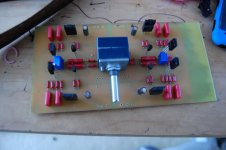
buzzforb; a great piece of art too. Love itIll give it a listen how I have it now and reduce Rs if I like what I hear. It is driving the F5TV2 that will go to my brother, so the low Zo should not be a problem. I had to parallel resistors to get values needed.
Best regards
Thermal drift - read this:...What would cause the instablity, otherwise?...
ken-gilbert.com/images/pdf/erno_borbely_on_jfets.pdf
I have both of his papers in permanent file. My question is, why if f5 output stable and this preamp prone to drift? Both have feedback, which should help. The F5 has the Thermistor in the bias arrangement, but I have built your Toshiba version without it. Built other comp Jfet circuits that didnt have stability issues.
Side not3. Is the 1uF cap necessary. I left it out assuming it was just a safety measure.
Side not3. Is the 1uF cap necessary. I left it out assuming it was just a safety measure.
... why if f5 output stable and this preamp prone to drift?
maybe because F5 output have a big heat sink controlling temperature 😉
but your pre only have wimpy small TO-92 BC550/560 .... maybe it would help to heatsink them
could be like just putting them into holes drilled in a mutual alu bar, or copper
UPS! I see you have changed those...right ?
hey...looks like it would be very easy to heatsink those substitute KSA/KSC 😀
They have KSa1381/3503 on heatsinks. Juma was eluding to the Jfets, based on the article he sent me, but perhaps I misunderstood.
...why if f5 output stable and this preamp prone to drift?...
If you look very carefully you'll notice certain dissimilarities between F5 and this preamp 😉
1. F5 has trim-pots in the MOSFETs' gate circuits to adjust symmetrical working of the output stage. In this preamp, the trim-pot is in JFETs' gates circuit so symmetrical working is set or ruined by JFETs.
2. Also, F5 is employing NTCs in the gate circuit in order to compensate for thermal drift and that's beautifully explained in F5 service manual (which you also have in your file repository I suppose).
3. F5 has MOSFETs at output and this preamp has BJTs - I leave to your knowledge hungry spirit to investigate differences in thermal behavior between these two types of devices (which is nicely covered in numerous educational writings).
So Buzz buddy, it's nice to have all the books, but reading them is irreplaceable... 😀
2. The lack of ntc's was mentioned, thank you.😛
So the crux of the matter is the bjt's in the output. Their biasing and thermal tendencies are what add that irritating touch that requires more reading(bla). Although I cannot argue about the lazy issue, understanding bjt's is not a single sitting affair and I did mention my ignorance before hand.
I redesigned the board to allow thermal coupling of the Jfets, per your suggestion. I am out of town for next week, so ill read up and redo when I get home.
Who knew a simple circuit could be so hard
BJTs have their share here, but in this circuit they are not under great thermal stress.
Item nr 1. from post #376 is crucial. Input stage's tendency to drift with temperature is more important. It would be great to match JFETs and operate them at zero tempco but it would demand a lot of work and a lot of parts - next best thing is to use JFETs that belong to same Idss group, couple them thermally and operate them in high Id region (as close as possible to zero tempco point). When everything is done correctly it's easy to achieve very low drift (+/-1mV difference between cold and hot state).
You were asking about 1uF cap at the input - I drew it only as a safety measure against DC leaking signal sources. That brings me to another point - all this thermal drift setting can be cumbersome because it depends on JFETs you got. Anyway, the easy cure is a nice 1uF coupling cap (WIMA MKP10 for example) at the preamp's output - it won't degrade the sound with F5T and will give you a permanent peace of mind.
It's easy to try, you'll be surprised
WIMA MKP10 1,0uF 630V :: MKP10 :: WIMA :: Film Foil :: Capacitors :: Passive Components :: Electronic Parts :: Banzai Music GmbH
WIMA MKP10 400V 1uF P=20 Polypropylene Capacitor(10-Pack) $27.92 Free Shipping @GoodLuckBuy.com
I used 10ma Idss matched fets in what I am calling failure 1.1. Could get offset very close with only a little drift, but every time i plugged it into main amp, offset whet crazy ad popped a fuse.I think it was poor ground layout, as I know nothing of board layout. New redesig has fets positioned to thermally couple them and 1uF cap on input. Havig just listeed to a RIAA, caps i signal affect signature, without a doubt. Got some if I need them.
Just for the hell of it, how do you match for tempco. Seems like something that is good to know, if you dont mind.
Just for the hell of it, how do you match for tempco. Seems like something that is good to know, if you dont mind.
- all this thermal drift setting can be cumbersome because it depends on JFETs you got.
Anyway, the easy cure is a nice 1uF coupling cap (WIMA MKP10 for example) at the preamp's output.......
good to remember, in case.. 😀
- Home
- Amplifiers
- Pass Labs
- Preamp ideas for F5