Hello dear forum 🙂
I am helping a friend with his Elephant-project to prevent them from getting killed my humans. So the aim is to record Elephant rumbles (which is mostly infrasound (<20Hz)) with a network of microphones, which calculates their location. (GPS collars are not really animal friendly and costly).
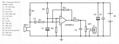
Sooo. I got this circuit which supposed to work. It's a preamp and low pass filter which attenuates frequencies above 150Hz.
I build it and i get this high pitched noise. (Soundsample)
Unfortunately i am not smart enough with electronics to find out the reason. I used audio-grade capacitors and checked all the connections and wirings twice (but of course never 100% sure).
Where does this high pitched noise come from? What can i do to find out about it?
That would be great if someone can help me out. I am sure the elephants will thank you for it
ED
I am helping a friend with his Elephant-project to prevent them from getting killed my humans. So the aim is to record Elephant rumbles (which is mostly infrasound (<20Hz)) with a network of microphones, which calculates their location. (GPS collars are not really animal friendly and costly).
Sooo. I got this circuit which supposed to work. It's a preamp and low pass filter which attenuates frequencies above 150Hz.
I build it and i get this high pitched noise. (Soundsample)
Unfortunately i am not smart enough with electronics to find out the reason. I used audio-grade capacitors and checked all the connections and wirings twice (but of course never 100% sure).
Where does this high pitched noise come from? What can i do to find out about it?
That would be great if someone can help me out. I am sure the elephants will thank you for it
ED
Attachments
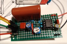
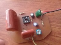
This is a picture from a working prototype which was built 5 years ago from a University in Sri Lanka (where i got the circuit from). They used bigger capacitors (same capacity but bigger in size). It would surprise me if that matters. But does size really matter? 😀
Attachments
The tone seems to be 4096Hz and its harmonics, a suspiciously power-of-two frequency suggesting it is interference from some digital circuitry near the microphone or amplifier? (Audacity is a handy tool to have!)
Mic amps need to be in a screened box, and mic cables need to be screened, as they are very sensitive to interference.
Actually given the low-pass filtering perhaps the interference is getting in after the amp, or to the signal ground line?
Mic amps need to be in a screened box, and mic cables need to be screened, as they are very sensitive to interference.
Actually given the low-pass filtering perhaps the interference is getting in after the amp, or to the signal ground line?
I think the schematic is correct (standard inverting AOP). But you're right there is maybe an oscillation. You should populate R5 (10 to 50 ohms) to drive capacitive load. Could you reduced C2 (then increase RV1 to have same fc) ? You could try to add a small cap in // with R3 (100pF for example).
OK. I think best way to correct the circuit is:
- remove C2
- add a cap in // with R3 (low pass filter). This cap in // with R3 is the same think than C2 in // with VR1. As VR1 is < 10xR3 -> C in // with R3 can have a value = C2/10 (100pF)
- Add a cap in series with R5 (between R5 and VR1) because there is a DC voltage at output. DC block is missing.
The tone seems to be 4096Hz and its harmonics, a suspiciously power-of-two frequency suggesting it is interference from some digital circuitry near the microphone or amplifier? (Audacity is a handy tool to have!)
Mic amps need to be in a screened box, and mic cables need to be screened, as they are very sensitive to interference.
Actually given the low-pass filtering perhaps the interference is getting in after the amp, or to the signal ground line?
I looked at the frequency with Audacity and it really is around 4100Hz.
The mic is connected with a 10cm wire. But even i pack it all up in a metal box. Or place it further away from other electric devices. There is no change of the output signal.
Nice. I learned about feedback in amps. Thanks for that hint. "Sounds" like this can be the problem. I checked the wiring again. Specifically around R3. But can't see a mistake.My guess is that the feedback circuit is connected incorrect (creating an oscillator instead).
Great. Something to try. I will look into that tomorrow. Already after 2AM here.Kartapus said:I think the schematic is correct (standard inverting AOP). But you're right there is maybe an oscillation. You should populate R5 (10 to 50 ohms) to drive capacitive load. Could you reduced C2 (then increase RV1 to have same fc) ? You could try to add a small cap in // with R3 (100pF for example).
But just to be sure i understood correctly (I am a novice):
- R5 is just a wire (zero Ohm) right now. But i will change to 50-100Ohm
- I only have elcos here in different capacities. So must order first (any values in mind?)
- the 100pF in // to R3 should be foil or ceramic? (Need to buy or find on broken PCBs first)
I agree with Kartapus, it could be oscillating, and if it is, removing C2 or adding R5 (preferably 56 ohm) should help. Besides, an LM358 is about the worst op-amp there is for audio, because it creates cross-over distortion when its output has to draw more than 20 uA...50 uA of current.
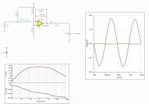
Please find simulation with TI-Tina (free). There is the original file to play on cap value to change bandwidth if necessary. Input is 50mV. Conclusion: works very fine as it.
Attachments
Last edited:
a last important remark because it is not done on my simulation. Please be aware to correctly bias the micro. See datasheet but value of R4 depends on current and voltage necessary for the microphone. A value of 10k under 9V could meet most of micro requirements but maybe it should be verified. If micro needs at least 5V with 1mA then R4 max = 9 - R4*I = 5 --> R4 = 4 kohms max.
All right. Cool.OK. I think best way to correct the circuit is:
- remove C2
- add a cap in // with R3 (low pass filter). This cap in // with R3 is the same think than C2 in // with VR1. As VR1 is < 10xR3 -> C in // with R3 can have a value = C2/10 (100pF)
- Add a cap in series with R5 (between R5 and VR1) because there is a DC voltage at output. DC block is missing.
Novice recap:
- Remove C2
- Add 100pF // to R3
- Add R5 (50 - 100 Ohm)
- The cap in series with R5 has to be which value? Foil, ceramic, electrolytic?
About the simulation software. Looks too sophisticated to me. But i will check it tomorrow too 🙂
Besides, an LM358 is about the worst op-amp there is for audio, because it creates cross-over distortion when its output has to draw more than 20 uA...50 uA of current.
Can i just change to a better one? You have one in mind?
100pF ceramic is OK (npo/cog if possible). R5 is only necessary if the load is capacitive. With C2 it is the case. Remove C2 because C3 plays the same think as C2 (low pass filter). So R5 can stay at 0R.
Can i just change to a better one? You have one in mind?
OPA1678 is pretty good and not too expensive, but there is no version in a DIP package.
Kartapus simulates with an OPA1642, which is also far better than an LM358 and not available in a DIP package.
By the way, cool project!
Single : OPA1671, OPA1641, OPA134, OPA604
Dual : OPA1692, OPA1642, OPA1678, OPA1688, OPA1652, OPA1656, OP1612, OPA2132, NE5532A (this one should exist in DIP)
All theses OP Amps are very good for audio.
Dual : OPA1692, OPA1642, OPA1678, OPA1688, OPA1652, OPA1656, OP1612, OPA2132, NE5532A (this one should exist in DIP)
All theses OP Amps are very good for audio.
Last edited:
I didn't think of an NE5532 because of the low supply voltage, but you are right, an NE5532 should still work at an asymmetrical 9 V supply. The same holds for the TL071, TL072 or TL074 (which have a higher noise level than the more modern op-amps, but probably still good enough).
Hello dear forum 🙂
I am helping a friend with his Elephant-project to prevent them from getting killed my humans. So the aim is to record Elephant rumbles (which is mostly infrasound (<20Hz)) with a network of microphones, which calculates their location. (GPS collars are not really animal friendly and costly).
Sooo. I got this circuit which supposed to work. It's a preamp and low pass filter which attenuates frequencies above 150Hz.
I build it and i get this high pitched noise. (Soundsample)
Unfortunately i am not smart enough with electronics to find out the reason. I used audio-grade capacitors and checked all the connections and wirings twice (but of course never 100% sure).
Where does this high pitched noise come from? What can i do to find out about it?
That would be great if someone can help me out. I am sure the elephants will thank you for it
ED
Where is the output DC blocking cap? The DC value on the opamp should be 1/2 B1. What is with the second
opamp? Are you using it or is it just 'dangling'. It could be your problem. Tie pins 6&7, tie pins 5&3.
G²
Just had a similar problem with am op amp circuit in a transistor tester.
The op amp didnt like the 100k feedback resistor and needed a capacitor across the 100k to make it stable. I used 220pf.
The op amp didnt like the 100k feedback resistor and needed a capacitor across the 100k to make it stable. I used 220pf.
So the aim is to record Elephant rumbles (which is mostly infrasound (<20Hz)) with a network of microphones, which calculates their location. (GPS collars are not really animal friendly and costly).
How low is the lowest frequency of interest? That's important for calculating the required coupling capacitor values.
I really appreciate all your help. That is awesome. I will try the solutions which needs extra parts after i got them shipped here which might take some days (i am on Sumatra far from any city...)
They were in "dangling" mode... but after connecting them. Still same problem.
Just talked to our Elephant guy and he said: in general 10Hz but some go down to 5Hz
Are you using it or is it just 'dangling'. It could be your problem. Tie pins 6&7, tie pins 5&3.
They were in "dangling" mode... but after connecting them. Still same problem.
MarcelvdG said:How low is the lowest frequency of interest? That's important for calculating the required coupling capacitor values.
Just talked to our Elephant guy and he said: in general 10Hz but some go down to 5Hz
Please find simulation with TI-Tina (free). There is the original file to play on cap value to change bandwidth if necessary. Input is 50mV. Conclusion: works very fine as it.
C3/R3 = High Pass Filter fc = 1/2.PI.R.C
C1/R6 = Low Pass Filter (improvement of phase margin by reducing the bandwith at high frequencies)
C2/P1 = High Pass Filter
- Home
- Source & Line
- Analog Line Level
- Preamp for Mic for makes high pitched noise