Hi, PMA,
This one seems not coming from you. Lack of PMA characteristic 😀
You dont use differential or CCS for the first stage?
Is this better than your openloop I/V converter?
Hi, all,
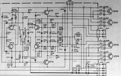
I have a question about Diamond buffer used as power amp output stage. From some examples, I see 2 kind of DB used for power amp. One is CCS feeding (like the one here and also Walt Jung), the other is only R loading, like this one I attach. It comes from a respectable sounding Marantz. Using 7W 8K2 plain resistor, even without bootstrapping.
What is the pro/con between using CCS and R for feeding diamond buffer?
2nd. Is it necessary to put Capacitance between upper and lower diamond buffer? The Marantz has 2 x 10uF cap around DB, while Walt Jung uses none. Again, what is the pro/con between these 2?
This one seems not coming from you. Lack of PMA characteristic 😀
You dont use differential or CCS for the first stage?
Is this better than your openloop I/V converter?
Hi, all,
I have a question about Diamond buffer used as power amp output stage. From some examples, I see 2 kind of DB used for power amp. One is CCS feeding (like the one here and also Walt Jung), the other is only R loading, like this one I attach. It comes from a respectable sounding Marantz. Using 7W 8K2 plain resistor, even without bootstrapping.
What is the pro/con between using CCS and R for feeding diamond buffer?
2nd. Is it necessary to put Capacitance between upper and lower diamond buffer? The Marantz has 2 x 10uF cap around DB, while Walt Jung uses none. Again, what is the pro/con between these 2?
Attachments
By the time I have built (not only simulated) the amp shown here in http://www.diyaudio.com/forums/showthread.php?postid=730220#post730220
The amp is pretty fast, F(-3dB) = 3MHz. It does not need the output RC correction as shown. It is stable, drives pure 1500pF load without problem, with square signal tr = 10 ns at the input. Step response is without overshoot, with 1500pF load the overshoot is about 20%. Sine wave of 3MHz is pure at the output, undistorted. Output impedance is low, about 4 Ohm. It drives even 50 Ohm load. I will give it a chance and will make a preamp based on this circuit. Simplicity makes sense.
The amp is pretty fast, F(-3dB) = 3MHz. It does not need the output RC correction as shown. It is stable, drives pure 1500pF load without problem, with square signal tr = 10 ns at the input. Step response is without overshoot, with 1500pF load the overshoot is about 20%. Sine wave of 3MHz is pure at the output, undistorted. Output impedance is low, about 4 Ohm. It drives even 50 Ohm load. I will give it a chance and will make a preamp based on this circuit. Simplicity makes sense.
lumanauw said:Hi, PMA,
This one seems not coming from you. Lack of PMA characteristic 😀
You dont use differential or CCS for the first stage?
I wanted to build quite fast and very stable stuff for now, for this reason I did not use global feedback, CCSs, mirrors etc. I am interested in sound result of this approach. I kept class A. The circuit has quite a lot of gain if needed, this is set by resistors between emitters of the input differential stage. DC is set by resistor between collector of the 2nd transistor and ground.
lumanauw said:
I have a question about Diamond buffer used as power amp output stage. From some examples, I see 2 kind of DB used for power amp. One is CCS feeding (like the one here and also Walt Jung), the other is only R loading, like this one I attach. It comes from a respectable sounding Marantz. Using 7W 8K2 plain resistor, even without bootstrapping.
What is the pro/con between using CCS and R for feeding diamond buffer?
2nd. Is it necessary to put Capacitance between upper and lower diamond buffer? The Marantz has 2 x 10uF cap around DB, while Walt Jung uses none. Again, what is the pro/con between these 2?
David,
as you know, I also built a diamond buffer based power amp with R feeding, see http://www.pha.inecnet.cz/macura/next.htm. Though CCS should be superior due to maintaining the constant current even for large output swings, the results do not seem to be that different. The capacitor between bases in my circuit reduces distortion and helps the transition to class AB, if needed.
I don't like plenty of parts too, capacitors especially 🙂 But - what is your opinion about thermal distortions importance (I mean active parts outside global NFB loop, as in your case, as you have not global NFB 😉)?Originally posted by PMA ... Simplicity makes sense.
PMA said:It is stable, drives pure 1500pF load without problem, with square signal tr = 10 ns at the input. Step response is without overshoot, with 1500pF load the overshoot is about 20%.
I made a mistake here, I was speaking about 15 000 pF load. Verified also for 47 000 pF, no problem.
anli said:I don't like plenty of parts too, capacitors especially 🙂 But - what is your opinion about thermal distortions importance (I mean active parts outside global NFB loop, as in your case, as you have not global NFB 😉)?
I know what you are speaking about and I have read those articles. Frankly speaking - I do not know.
I have read an artcicle by russian author also, unfortunately, in Russian only:
http://www.aml.nm.ru/reasons.htm
http://www.aml.nm.ru/reasons.htm
anli said:I have read an artcicle by russian author also, unfortunately, in Russian only:
http://www.aml.nm.ru/reasons.htm
Thank you Andrej, russian is no problem for me.
Pavel, I'd want to prepare to read this athor (AML) articles. Some of them are very disputable 🙂 As for me, I can not accept many AML's conclusions.
Simplicity makes sense.
I wanted to build quite fast and very stable stuff for now, for this reason I did not use global feedback, CCSs, mirrors etc.
PMA, really, what has happened to you? 😀 Is this the same PMA that adores Halcro?
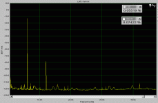
PMA said:And here is the spectrum of the circuit. As Nelson says, "distortion is almost purely 2nd harmonic". It does not depend on frequency in the audio band, same for 1kHz as for 10kHz.
means that origin of it from third bjt which is between symmetric input and symmetric output.
Now for 100 mV:
1 -12dB
2 -79 dB
3 -120 dB(?)
and due to exponential BJT for 500 mV INPUT:
1 +2dB
2 -51 dB
3 -70 dB (approx)
for 1000 mV INPUT:
1 +8dB
2 -38 dB
3 -45 dB (approx)
4 -55 dB (approx)
and a fifth quite high
Is it not too much even for 500 mV?
Noname,
I did not get the point of your post. Regardless your presumptions, I have measurements up to 8Vp-p at the output, which is about 20dB above the point when my power amp will go to limitation.
I did not get the point of your post. Regardless your presumptions, I have measurements up to 8Vp-p at the output, which is about 20dB above the point when my power amp will go to limitation.
PMA said:100mV, 4x, +/-12V.
100 mV input 400 mV output for the spectrum presented.
Is it a maximum signal level you plan to use?
- Status
- Not open for further replies.
- Home
- Amplifiers
- Solid State
- Preamp concept