I used to find that while manuals could have errors, or if the circuitry seemed to differ in parts from that shown in the correct service manual then the product itself was always assumed correct in itself and the reason was either pure error in the printed manual, or the production run had been modified to account for issues that had come to light in service.
It also used to be common to see manuals that applied to certain runs of serial numbers with a separate different manual (or an insert for the manual) covering another run of serial numbers.
So I think your preamp will be all correct electrically but the manual has errors.
It also used to be common to see manuals that applied to certain runs of serial numbers with a separate different manual (or an insert for the manual) covering another run of serial numbers.
So I think your preamp will be all correct electrically but the manual has errors.
I tried the simplified feedback loop, and that introduced a loud earth hum (which is quite possible came from the way I wired it up) that masked any effect there may have been on the underlying hiss.
I'm coming back to my observation about the volume control being very sensitive - I don't need to turn the volume up much above 10% for the output volume to match the volume bypassing the preamp entirely - and wondering if the overall gain is more than it should be, and something in the feedback loop has gone wrong to increase the gain and hence cause both behaviours. Given that all the resistors measure correctly, I'm not sure how that could happen though?
I'm coming back to my observation about the volume control being very sensitive - I don't need to turn the volume up much above 10% for the output volume to match the volume bypassing the preamp entirely - and wondering if the overall gain is more than it should be, and something in the feedback loop has gone wrong to increase the gain and hence cause both behaviours. Given that all the resistors measure correctly, I'm not sure how that could happen though?
It would be highly unlikely to have the same kind of fault on each channel if you worked to the theory that something is wrong somewhere.
Look at the circuit... the gain is set by the feedback factor which in this case is determined by the tone control components.
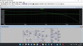
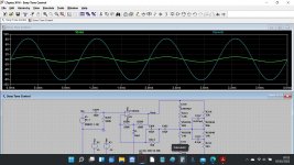
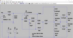
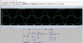
Here is a simple version of how it works. Look at the opamp at the left. The gain is set precisely by Rf and R1 and equals Rf/R1 + 1 which is a gain of 5. If you look at the input and output voltages on the 'scope trace' at the top you can see that holds true.
If we make the values 800k and 200k the gain is still the same but now the circuit would be noticeably noisier because of the high impedance of the network.
In your circuit C205 connects to the feedback network. The HA12017 although an opamp needs a bit more paraphernalia around it but the principle is the same.
The voltage gain is about 7 numerically on the line inputs. That's high by modern standards where source components like CD players output a couple of volts as standard compared to around 200 millivolts for older DIN standard gear.
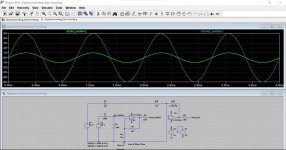


Given what you said, I thought it would be a good idea to connect the matching tuner. Even with the matching tuner as the source, the volume still gets very loud very quickly, which suggests that something's up. (I don't have the matching speakers
Additionally, with the volume turned up to around 30%, the preamp will cause my Mitsubishi M-A01 power amp to trip with the peak level meters only showing around 0.1W (they go up to 100W). When I play music from my DAC, I can drive the amp a lot harder. That's an unscientific measurement, I know - but it shows that the preamp is doing something it shouldn't.
(The Sony TAN-15F expects input of 1.1V and has impedance of 22kohm; the Mitsubishi M-A01 expects 1V input and has impedance of 50kohm. I think we can eliminate the different power amps as a factor in the behaviour of the preamp. I'm not using the Sony power amp in my investigation because it's in bits due to me trying to silence its noisy transformer.)
In the name of trying to be more scientific, I did some measurements with the scope:
By way of comparison, to get 0.1W of output out of my Mitsubishi amp, my DAC outputs 100mV (16mVrms measured). If I switch off the speaker outputs to avoid deafening myself, turning it up to 2V peak-to-peak or 0.3Vrms measured will get the amp to show 25W of power output, which is way higher than the power output it shows with the Sony preamp connected before the protection circuit trips.
It seems to me like something's not right somewhere, but I can't put my finger on it. The preamp definitely shouldn't cause my power amp to trip, and I think that's the biggest clue - but I don't know what it's pointing towards, especially bearing in mind the measurements.
Additionally, with the volume turned up to around 30%, the preamp will cause my Mitsubishi M-A01 power amp to trip with the peak level meters only showing around 0.1W (they go up to 100W). When I play music from my DAC, I can drive the amp a lot harder. That's an unscientific measurement, I know - but it shows that the preamp is doing something it shouldn't.
(The Sony TAN-15F expects input of 1.1V and has impedance of 22kohm; the Mitsubishi M-A01 expects 1V input and has impedance of 50kohm. I think we can eliminate the different power amps as a factor in the behaviour of the preamp. I'm not using the Sony power amp in my investigation because it's in bits due to me trying to silence its noisy transformer.)
In the name of trying to be more scientific, I did some measurements with the scope:
- the tuner outputs roughly 1.3V peak-to-peak (0.15Vrms measured) when tuned;
- at the preamp output, peak-to-peak voltage is about 2V (0.3Vrms measured) at 30% volume;
- with the preamp at full volume, peak-to-peak voltage is about 9V (1.3vrms measured).
By way of comparison, to get 0.1W of output out of my Mitsubishi amp, my DAC outputs 100mV (16mVrms measured). If I switch off the speaker outputs to avoid deafening myself, turning it up to 2V peak-to-peak or 0.3Vrms measured will get the amp to show 25W of power output, which is way higher than the power output it shows with the Sony preamp connected before the protection circuit trips.
It seems to me like something's not right somewhere, but I can't put my finger on it. The preamp definitely shouldn't cause my power amp to trip, and I think that's the biggest clue - but I don't know what it's pointing towards, especially bearing in mind the measurements.
Have you had the scope set to DC coupled when looking at the output at the time the power amp trips? That might show something odd happening, either constant DC or a sudden shift up or down (which means the DC conditions in the preamp suddenly change) , Definitely worth checking. Even a small sudden shift could be interpreted by the power amp as a DC offset and cause the trip.
Also look to make sure the preamp output has no HF oscillation anywhere on the output when the power amp trips.
The volume level vs rotation of the control might be normal. It would or could be seen as a marketing gimmick showing how 'loud' it can go. Like the small car with the speedo that goes up to 160mph.
Irritatingly, I now can't reproduce the problem. Probably it will have been due to some DC offset, as I've seen that behaviour before. I think my methods for bench testing this preamp aren't up to scratch, and whilst just applying an attenuator to the output would be a workaround rather than a solution so feels rather like giving up, that's my best chance of achieving a satisfactory outcome.
I guess it's either that or try a different opamp to see if it behaves differently. I have an NJM5532 lying around that I wouldn't be too upset about losing - that would be operating on the edge of its +/-22V limit, but it'd be enough to show how much the opamp itself is contributing to the issue. I'd just need to wire it up to test it in a way that doesn't pick up too much interference from the nearby transformer, as happened when I tried to test the simplified feedback loop.
I guess it's either that or try a different opamp to see if it behaves differently. I have an NJM5532 lying around that I wouldn't be too upset about losing - that would be operating on the edge of its +/-22V limit, but it'd be enough to show how much the opamp itself is contributing to the issue. I'd just need to wire it up to test it in a way that doesn't pick up too much interference from the nearby transformer, as happened when I tried to test the simplified feedback loop.
That can be done. Do you have any single opamps like a TL071 although a 5532 is OK although you shouldn't really leave the unesed section floating?
The supply voltage is easy to alter by reducing R303. I think a 10k should give something around -/+16 volts. No need to remove R303, just tag a 22k across it and see what the rails come out at.
If you remove the opamp then a new one can be tagged in very easily.
The supply voltage is easy to alter by reducing R303. I think a 10k should give something around -/+16 volts. No need to remove R303, just tag a 22k across it and see what the rails come out at.
If you remove the opamp then a new one can be tagged in very easily.
- Home
- Amplifiers
- Power Supplies
- Preamp bias voltage is smaller than it should be
