I used some Beovox CX50 speakers to test; I also have some Dali Trio speakers that I've used; I think they're both in the high 80s dB/watt response.
As for testing, I do have a random selection of resistors, I think from 56 ohms to 56k, and I have a laptop I can use to play an MP3 file into the preamp.
As for testing, I do have a random selection of resistors, I think from 56 ohms to 56k, and I have a laptop I can use to play an MP3 file into the preamp.
I'll do an MP3 file for you now, high 80's db is not that high in the scheme of things. I was thinking of horns and maybe 110db/watt where hiss would be very noticeable.
Give me a minute.
Give me a minute.
Here we go. It doesn't quite reach 20k because of MP3 limitations and keeping the file size small but it should be fine. It starts at 20Hz. On the scope the amplitude should be constant as the frequency rises and that should be the same after passing through the amp with the tone controls centred.


Attachments
Thanks! I tried it out and the frequency sweep looks pretty even all the way through - it starts maybe 10% higher then amplitude is constant from 300Hz.
While I was there with everything hooked up, I tried two other things and noticed a couple of curious behaviours: when turning the volume knob from zero to full, what sounds like ground hum interference increases up to the midway point then subsides until it all but disappears at full volume. Similarly, when adjusting the balance from centred to fully on one side, the same thing happens only louder: the sound increases until the balance is midway towards that speaker, then subsides until it disappears when the balance is fully towards that speaker. Something is resonating but I don't yet know what...
Here's a link to a video of how it went. In case it helps, here's the full service manual which contains board traces as well as the diagrams I've posted snippets from.
So it looks like the tone controls are OK given the overall response is flat. Tbh I think your scope is a bit of a limiting factor here as it tries to auto range with the changing signal 🙂
We're still no nearer then. As I mentioned earlier, this is really hard to get a feel for without actually hearing the hiss for real.
The hum varying up and down with the balance and volume control is something I've encountered with early diy amps I've built and it can be down to less than perfect grounding arrangements.
It can also occur because at low volume and high volume the wiper of the control is at its lowest impedance. The volume control wiper for example is near ground at lower levels and near the incoming input at higher levels. That means the wiper and circuitry connected to it is more susceptible to hum pickup at the mid travel region.
Usually grounding issues within the circuitry show up as 100 or 120 Hz hum (twice mains frequency) and often has a harsh edge or buzz to it ,whereas induced hum would be 50 or 60 Hz and is much purer and deeper sounding.
I'm running out of easy ideas here 🙂
If you are just interested in trying a few things out then you could easily remove the opamps and link pin 6 to pin 1. That would pass the signal through like a passive preamp but you might see if you still get hum pickup.
Also and depending how sensitive your scope is you could try looking at the signal on R206 going into the opamp with no signal applied. Can you see hum and noise there for example and does it change with the volume control?
Edited. lowest, not highest as I originally typed.of the control is at its lowest impedance
I retested the grounding issue with the inputs shorted and it didn't happen, so I guess that was a grounding issue with the laptop, and a bit of a red herring. So I'm back to looking for the original interference.
Measuring against ground, with the inputs shorted, I can see that there is already noise introduced immediately after the volume control, as compared to the input contact, with the volume control at zero.
With the volume at full there's around 15mV of noise at the output of the volume control, and the results are similar after the balance control, after R206, and at the opamp input. The noise is not present on the input side of R121, but is present immediately after R121 even with the volume off.
So, the noise is measurable at the junction of R121, the input to the volume pot, the collector of the muting transistor Q405, and a wire going to the loudness switch board which, since loudness is switched off, is a dangling 33k resistor. The same is true of the right channel with muting transistor Q406.
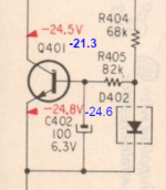
Since interference increases as volume increases, a source of some of the interference must be at the aforementioned junction. Which means that the muting transistor must surely be the source... but I tried shorting across it, and that made very little difference. Maybe there was slightly less, but it wasn't perfect. I looked at the voltage going into the muting transistor, and in addition to being a few volts less than it should be (-21.something instead of -24.5) it's fluctuating +/-0.2V at 50Hz.
There are similar muting transistors on the output stage, too - which I obviously can't test without removing, as shorting the collector to the emitter mutes the output!
Does it make sense to test the behaviour with the muting transistors on the input and output stages removed, to eliminate a possible cause of the interference? They're the only other active components in the signal path apart from the opamp.
Measuring against ground, with the inputs shorted, I can see that there is already noise introduced immediately after the volume control, as compared to the input contact, with the volume control at zero.
With the volume at full there's around 15mV of noise at the output of the volume control, and the results are similar after the balance control, after R206, and at the opamp input. The noise is not present on the input side of R121, but is present immediately after R121 even with the volume off.
So, the noise is measurable at the junction of R121, the input to the volume pot, the collector of the muting transistor Q405, and a wire going to the loudness switch board which, since loudness is switched off, is a dangling 33k resistor. The same is true of the right channel with muting transistor Q406.
Since interference increases as volume increases, a source of some of the interference must be at the aforementioned junction. Which means that the muting transistor must surely be the source... but I tried shorting across it, and that made very little difference. Maybe there was slightly less, but it wasn't perfect. I looked at the voltage going into the muting transistor, and in addition to being a few volts less than it should be (-21.something instead of -24.5) it's fluctuating +/-0.2V at 50Hz.
There are similar muting transistors on the output stage, too - which I obviously can't test without removing, as shorting the collector to the emitter mutes the output!
Does it make sense to test the behaviour with the muting transistors on the input and output stages removed, to eliminate a possible cause of the interference? They're the only other active components in the signal path apart from the opamp.
It might be worth a look at the muting circuit although its hard to see how that could generate hiss. It could possibly add hum though.
Rather than pull the transistors (you can pull them all out if you want) you could try looking with the scope at the voltage across C401 in the power supply (should be fairly clean) and also the mute voltage applied to the mute transistor bases's.
The voltage across C403 should be clean. It is shown as -24 volts which doesn't quite compute tbh for being applied to a base/emitter junction (the mute transistors) unless the 2SC1636 has inbuilt bias resistors. The circuit mutes when the voltage goes positive and turns the transistors on. Again, with a regular transistor that voltage would limit at around 0.6 volts.
I can't find a data sheet on those transistors but they could be pre-biased.
The voltage across C401 (-25V, as it should be) isn't very clean. It's not even a clean sawtooth!

The voltage across C403 (-21.7V, should be -24.5) isn't very clean either.

In the name of learning something I pulled the muting transistors from one channel, and the only difference it made is introducing a very slight ground hum on the input side, and of course a pop when switching off. (The amplifier has a switch that reverses the channels just before the balance control, and when I reversed the channels, the ground hum went to the other speaker, so I know where it's coming from.) So at least I can now rule out the muting transistors as the source of the noise.
The voltage across C403 (-21.7V, should be -24.5) isn't very clean either.
In the name of learning something I pulled the muting transistors from one channel, and the only difference it made is introducing a very slight ground hum on the input side, and of course a pop when switching off. (The amplifier has a switch that reverses the channels just before the balance control, and when I reversed the channels, the ground hum went to the other speaker, so I know where it's coming from.) So at least I can now rule out the muting transistors as the source of the noise.
What you see on the scope is probably normal and those caps are small in value by design to give a fast mute action. Its not super clean but clean enough. So its going to be OK.
-24 volt on the transistor full turns it off (and they must be pre biased types to allow that voltage to appear across them). The small ripple superimposed on that -24v doesn't make any difference, it is off whether -10, -20, -30 volts were present and even if it varies between those levels.
I really don't know what to suggest and given the seemingly high levels of noise you measure I really wonder whether that is partly down to measurement anomalies in some way. Those figures are massively high and would be extremely loud after passing through the opamp with its high gain and then on to the power amp.
Why not pull the opamps out and link the opamp out and first of all see if it is silent used this way, firstly with the power off and then with it powered up.
Just a wild guess, but doesn't this look like mains frequency (plus harmonics)? Are all ground connections good? Supply filter caps ok?I took some more scope readings, and I noticed that the noise had something of a pattern to it:

and when the treble controls are turned all the way down, it stabilises into this (note the different time scale):

Also the voltage difference in the attached image seems much higher than it should be ...
Attachments
Last edited:
If this was a regular 8-pin DIP opamp I'd have pulled it right away, but this is some obscure no-longer-available thing that's making me a little (irrationally?) wary. I mean, I'm not a soldering genius but it's not beyond my capability - I just wanted to try everything else first.Why not pull the opamps out and link the opamp out and first of all see if it is silent used this way, firstly with the power off and then with it powered up.
What I'd love is for there to be a quick way to take the tone control circuit out of the equation, but sadly not. I'm going to do some measurements on that, then I'll come back to this idea later.
I'm definitely going to have to pull the opamp (hopefully later today) as I can't get my head around what it's doing. I can't find a datasheet for the CX-550 opamp anywhere; the only other chip with a similar pinout is the Hitachi HA1457W; and probably its pins 3 and 5 behave differently than the Sony's (at least, the datasheet shows them being used differently).
For my own curiosity I measured what's going on around the opamp.
The -21V and +21V pins 4 and 8 are clean enough, with only a few millivolts of fluctuation:


Tone input pin 7 shows the interference pattern:

Input 6 is very quiet when there's nothing connected to the output - the 5mV noise only appears when there's an output connected:

Not-sure-what-it-does pin 5 looks similar to +21V pin 8 but has some interference on it (this measurement taken with nothing connected to the output; the noise is more visible with an output connected)

pin 3 is doing much the same as pin 7:

Pin 1 (output) looks a lot like input pin 6 - with no output it's very quiet, but with an output there's around 8mV of noise.
Next step will be to take the opamp out of the equation, I guess - which would also remove the effect of the tone controls. I guess removing C205 with the opamp in place would isolate the tone controls?
For my own curiosity I measured what's going on around the opamp.
The -21V and +21V pins 4 and 8 are clean enough, with only a few millivolts of fluctuation:
Tone input pin 7 shows the interference pattern:
Input 6 is very quiet when there's nothing connected to the output - the 5mV noise only appears when there's an output connected:
Not-sure-what-it-does pin 5 looks similar to +21V pin 8 but has some interference on it (this measurement taken with nothing connected to the output; the noise is more visible with an output connected)
pin 3 is doing much the same as pin 7:
Pin 1 (output) looks a lot like input pin 6 - with no output it's very quiet, but with an output there's around 8mV of noise.
Next step will be to take the opamp out of the equation, I guess - which would also remove the effect of the tone controls. I guess removing C205 with the opamp in place would isolate the tone controls?
The CX550 is in a SIL (single in line package) and although its an opamp, its an early non standard type. It is not beyond the impossible to replace it with something else but lets not go there yet.
Without having this in front of me it is really difficult to make definite conclusions over what is happening and so the best I can advise is to try and prove it by a process of elimination.
The opamps will come out in seconds with solder braid. As quick as typing these two sentences... honest 🙂
We can (I think) bypass the tone section quite easily while retaining the opamp but lets save that for later. Prove the thing is silent with no opamp in circuit first.
It's not taking the opamps out that I'm worried about, it's putting them back in again in working order 🙂 Mind you, if something happened to them, I can always borrow the ones from the phono stage.
I know what I'm doing later today then! I'll report back when I have some results.
I know what I'm doing later today then! I'll report back when I have some results.
To bypass the tone control... look at the circuit.
R208, R209 and C206 are not in the audio path. R209 and C206 form a filter that removes the audio content and derives an average DC value that is used for DC feedback to set the operating points.
You could simply add a new feedback network (two resistors) to bypass all the controls. A 22k and 1k in series from the opamp output to ground would give a gain of around 23 calculated as (22000/1000) +1. That would be a much lower impedance low noise network. The junction of the resistors is then AC coupled to pin 7 with a small cap. Lifting C205 then isolates the tone section.
You could remove and replace those a dozen times with no damage. A couple of seconds per pin to desolder and a second to resolder. They will be absolutely fine.
R208, R209 and C206 are not in the audio path. R209 and C206 form a filter that removes the audio content and derives an average DC value that is used for DC feedback to set the operating points.
You could simply add a new feedback network (two resistors) to bypass all the controls. A 22k and 1k in series from the opamp output to ground would give a gain of around 23 calculated as (22000/1000) +1. That would be a much lower impedance low noise network. The junction of the resistors is then AC coupled to pin 7 with a small cap. Lifting C205 then isolates the tone section.
It's not taking the opamps out that I'm worried about, it's putting them back in again in working order
You could remove and replace those a dozen times with no damage. A couple of seconds per pin to desolder and a second to resolder. They will be absolutely fine.
Something like this. Cap would be small electrolytic like a 10 or 22uF fitted to suit polarity that the opamp settles at.

I removed the opamp on one channel and that removed the hiss. There was some hiss at high volume but nothing at zero. There's some ground hum around the volume half-way mark, but right now the amp is open on the bench and the length of the temporary wire joining pin 6 to pin 1 could easily pick up hum from the transformer.
I did a bit of research and some random list of equivalents I found says that the Sony CX550 is the same as the Hitachi HA12017 (datasheet here). The datasheet is quite interesting as it shows what all the pins are for, details a test circuit, and explains the consequences of other surrounding components being out of spec.
Remember that hiss is caused by thermal noise in components and so if you have noticeable hiss with no opamp fitted then that hiss is coming from two sources, it comes from noise in front of the volume control (which should be pretty much zero if the input is shorted) and also noise from the volume control itself appearing in parallel (so appearing as a signal source) across the power amplifier input.
The high value of the volume control and balance control are something we would not see today.
So noise from in front of the control will be amplified by the gain of the opamp circuitry and the opamp itself also generates some noise. The output impedance of the opamp is low and that works in favour of reducing noise at the power amp input by appearing as a low impedance across the power amp input.
So no hiss at zero volume.
Do you want to try configuring the opamp with a low impedance feedback network as in post #37 as a test. You could try that with the oother channel to compare.
It might also be possible as a test to try a newer type of opamp literally hand wired into place. The supply voltage (-/+22v might need reducing a little if you do that... which is easy).
It all depends how far you you want to go with experimenting with this.
- Home
- Amplifiers
- Power Supplies
- Preamp bias voltage is smaller than it should be