I'm looking for reasons other than only the -2.0dB 20kHz droop being audible.Just a pre-warning, IMO observing any other DAC behavior changing dramatically simply tuning the effect from -.5dB to -1.5dB is highly unlikely. I also wish the jitter stuff was off the table it will make this a mess since the reasoning is very unsound.
Joe, what happens subjectively if you remove the extra supply decoupling caps and revert to original supply decoupling arrangement (third time asking).
Dan.
Depends on how you define data.
Measurements showing differences above audible thresholds and/or ears-only (no peeking) listening tests. That's how any rational and honest practitioner defines "data," it's not a definition exclusive to me.
Anecdotes are not data. Subjective does not mean uncontrolled.
I've had a little bit more of a look at this today and discovered that some of the Sony component values don't agree with those in the service manual (and it was those I based the original simulation on) although the difference it makes to the response is minor.
I suspect the values could have been rescaled to keep distortion at maximum levels to a minimum, the reason being that the opamps run on only -/+5 volts which is very low. The rescaled values slightly reduce the forward gain of the stage while maintaining the same response.
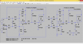
This diagram shows the values actually fitted in the DAC (left hand side of diagram) and on the final version I have settled on to test all this (right hand side of diagram). The components values I have selected mimic the original response as best as possible without recourse to odd values and making values up from series/parallel combinations. A check of the actual player output at 1kHz intervals all the way up to 20kHz shows a flat response. The fact that the final output is flat, implies that the DAC output is purposely not so given the fact the final opamp stage has this rising response characteristic.

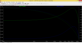
This diagram shows the response from the original values (as actually fitted) and my closest fit for the modification using preferred values that I had available. Apart from a slight overall reduction in output level it mirrors the original fairly closely I thought.

Listening tests tomorrow.
I suspect the values could have been rescaled to keep distortion at maximum levels to a minimum, the reason being that the opamps run on only -/+5 volts which is very low. The rescaled values slightly reduce the forward gain of the stage while maintaining the same response.
This diagram shows the values actually fitted in the DAC (left hand side of diagram) and on the final version I have settled on to test all this (right hand side of diagram). The components values I have selected mimic the original response as best as possible without recourse to odd values and making values up from series/parallel combinations. A check of the actual player output at 1kHz intervals all the way up to 20kHz shows a flat response. The fact that the final output is flat, implies that the DAC output is purposely not so given the fact the final opamp stage has this rising response characteristic.
This diagram shows the response from the original values (as actually fitted) and my closest fit for the modification using preferred values that I had available. Apart from a slight overall reduction in output level it mirrors the original fairly closely I thought.
Listening tests tomorrow.
Attachments
Measurements showing differences above audible thresholds and/or ears-only (no peeking)....
Anecdotes are not data. Subjective does not mean uncontrolled.
I understand the definition, it's the interpretation... not all data is quantitative and converting the subjective into 'numbers' or data is not without problems.
And you cannot eliminate all variables - you may think you have and then... and that was my epiphany. You cannot be forced to listen to a piece of music the same, not even twice.
My method is trying to trick them into thinking there is nothing to listen for. It's not textbook - which is good, or they would wisen up. Maybe that is why it may never become textbook. It is that blind. It's fun too. 😀
As I said, you have your method, perhaps approved by the orthodoxy and has some pluses, but I have gravitated away from it.
I've had a little bit more of a look at this today...
I am following this.
Steve Bolser has sent his - in his words - hand-made 1-bit impulse files as well as suggesting doing IM 18.5KHz & 19.5KHz tone tests as the filter is varied (cap value), like slices or slides. On the 1-bit files, will find out how he wants them used.
I ordered a M-Audio Audiophile 192 Professional Card in from the UK, they sent me an email that it was posted yesterday. I did that because I read that it is the same chipset as the Juli@ and "operationally they same" and that is what Steve Bolser uses, but the M-Audio much less cost in this instance.
Then I found that that this is also the sound card SY used for measuring and debunking Bybees. Not formed any real opinion about those and have not been attracted to use them, but my installer in New Zealand says he has and says they make little difference. "I am not interesting in small differences", to quote the late Allen Wright.
When people resort to using quantum mechanics explanations, is that code for "the rules in the sub-atomic world are such we don't have to explain how it works"? I just don't feel compelled to mount any crusades nor join one.
Joe, for all intents and purposes (and maybe intensive purposes 😉), it's probably best to stick with methodologies that are more straightforward and have ties to other, more rigorous, studies.
I don't doubt your sincerity, but your description leaves much desired from an ability to discern differences. Words like "trick into thinking" beg bias and injects dozen new variables that weren't there originally.
The M-audio192 is a solid, well-implemented sound card.
As for your latter point, I fear that'll get us on a direction that AJT requested we not.
As for your latter point, I fear that'll get us on a direction that AJT requested we not.
Hope not. But I am glad you said it. Shows awareness.
As long as we are respectful and can agree to disagree and see that the other person is not a robot but a person with a right to his point of view, then it is fine by me.
Last edited:
My method is trying to trick them into thinking there is nothing to listen for.
You should watch a few episodes of Penn and Teller's "Fool Us". Once tricking is allowed all bets are off. Why an effort to avoid a simple no peeking DBT? Any protocol, please don't bring up the ABX criticisms again.
You should watch a few episodes of Penn and Teller's...
Now that is taking a single word out of context.
I won't explain, it is clear it was simply a descriptive saying, no more. We can all pick on a single word and make an essay out of it.
There are three camps: The believers, the disbelievers and the agnostic. On this I am the last. That is not likely to change.
Last edited:
That is not likely to change.
Fair enough I'll move on for the sake of peace, but IMO that was a very direct declarative statement of purpose no ambiguity.
Fair enough I'll move on for the sake of peace, but IMO that was a very direct declarative statement of purpose no ambiguity.
I will move on too. But there will always be ambiguity, you cannot erase human nature.
Peace. 🙂
I understand the definition
Apparently not. If you have to peek, you can't hear it.
The 192 is an excellent card. It's extremely important to understand the variables in setup, in the measurements, and in the interpretation, otherwise you have a tool which will efficiently generate reams of nonsense.
Joe, what happens subjectively if you remove the extra supply decoupling caps (20uF ceramic//0.33F supercap) and revert to original supply decoupling arrangement (fourth time asking).
Dan.
This is exactly what cables like MIT do. They have in addition to complex parallel filters, simple series filters which roll off slightly around 20kHz. They do the same for interconnects, speaker cables, power cables, etc.
I can also hear this difference and I think it sounds great! My guess is that it has more audibly to do with time/phase distortion than just a bit of roll-off.
I've been using MIT for ages and don't plan on ever stopping. DACs are not the only components which benefit 🙂
I can also hear this difference and I think it sounds great! My guess is that it has more audibly to do with time/phase distortion than just a bit of roll-off.
I've been using MIT for ages and don't plan on ever stopping. DACs are not the only components which benefit 🙂
This is exactly what cables like MIT do. They have in addition to complex parallel filters, simple series filters which roll off slightly around 20kHz. They do the same for interconnects, speaker cables, power cables, etc.
I can also hear this difference and I think it sounds great! My guess is that it has more audibly to do with time/phase distortion than just a bit of roll-off.
I've been using MIT for ages and don't plan on ever stopping. DACs are not the only components which benefit 🙂
Can you please show some proof (measurement) of this... I've always believed MIT cables are flat through audio freqencies? 😕
Can you please show some proof (measurement) of this... I've always believed MIT cables are flat through audio freqencies? 😕
Measurements and proof are always hard, aren't they? I've owned and taken apart just about every MIT cable up until the Magnum line in the past 10 years. There are many pictures online if you google "MIT cables inside."
Just as an example, most MIT speaker cables (regardless of price) have a 10uH inductor in series. If you take a look at this article: Cross Coax Cables Design vs Zip Cord - Analysis | Audioholics
~10uH (50ft. times 0.191uH/ft.) of speaker cable inductance gives approximately a 0.7dB loss at 20kHz into a 4 Ohm load according to Spice. Spice is needed because these are very difficult calculations as the system consists of very low amplifier impedance and high speaker impedance.
MIT's interconnects have slightly lower value inductors, but I'm guessing the effect is the same.
In addition, all of MIT cables have what they call "filter poles." These are nothing but parallel RC circuits. Where C is usually in the pF range. But because a lot of their more expensive cables have 20, 30, 40, 50, and all the way up to 100+ RC networks, the total RC adds up significantly. It most certainly affects the 20kHz range, plus the series inductor.
You can read all of MIT Bruce Brisson's patents here: https://www.google.com/search?tbo=p&tbm=pts&hl=en&q=ininventor:"Bruce+A.+Brisson"&gws_rd=ssl
Bottom line is that MIT cables definitely apply loss at 20kHz as well as perform other attenuations to the signal. IMO they sound great and are something that can be used by anyone to test this thread's OP's theories. Without having to modify or build any components 🙂
Some images of MIT cables:
http://www.audiobility.co.uk/images/mitcableswhatsinthebox.jpeg
http://208.69.122.162/images/mit_cables_cvt_hybrid.jpg
http://cd8ba0b44a15c10065fd-24461f3...llaforums.com/attachments/6/5/6/4/3/39943.jpg
http://s159.photobucket.com/user/garcimol/media/002-6.jpg.html
http://s64.photobucket.com/user/dlechner/media/IMG_2264.jpg.html
http://s64.photobucket.com/user/dlechner/media/IMG_2272.jpg.html
http://www.6moons.com/audioreviews/mit2/multipole_parallelnetworks.jpg
http://www.hifishock.org/galleries/cable-accessories/cable/mit/ac-power-cable/magnum-ac1-mit-1b.jpg
Last edited:
I'm looking for reasons other than only the -2.0dB 20kHz droop being audible.
The key word you used here is other and yes.
Sorry, I kept getting distracted.
Joe, what happens subjectively if you remove the extra supply decoupling caps and revert to original supply decoupling arrangement (third time asking).
I do think what the SuperCap does is less of a mystery. Now I don't want to sound more expert than I am, but this is also something that Ted Smith from PS Audio has said: Since we have only two states and the delta-sigma modulator switched 'on' the rail, typically 3.3V or 5V, then any aberration, any noise even down to very LF, gets, in his words, converted to audible jitter at a most critical stage. So it is as important as purity of clock signal etc. Ted filter the PS down to 1 Hertz. The SuperCap is not a filter perse' - but it is a massive amount of energy to store that a kind of flywheel effect takes place, like a 'mass' filter rejecting change, if you can visualise it. Anyway, that is the thinking and others may view it a little differently.
The affect on sound? Again, just like the post-DAC filter, I have been cautious in describing, letting others do that. But if seems to add and makes what the post-DAC filter does better. Maybe like 1+1=3, as in 'more of the same.'
Hi Joe, thanks for answering.
Ok, my take on what is possibly going on.
The 1uF is indeed causing smoothing/slew reduction of the DAC outputs, but at the expense of increased power supply transient currents if indeed the DAC output is Pulse Density Modulated or Pulse Width Modulated.
You state that the supercap has internal resistance of around 75R, so it could be argued that the supercap is a zobel damping network covering down to very low frequencies, in addition to it's high energy storage capacity.
What happens if you connect only the 20uF ceramic cap...does this actually damage the sound due to power supply ringing perhaps ?.
Dan.
You state that the supercap has internal resistance of around 75R, so it could be argued that the supercap is a zobel damping network covering down to very low frequencies, in addition to it's high energy storage capacity....
What happens if you connect only the 20uF ceramic cap...does this actually damage the sound due to power supply ringing perhaps ?.
Dan.
You could be right on the Zobel, there could be something about that too, no the SMD only is something I have used for a long time and not just me, others to, including Coris using even higher amounts of stacked SMD caps. But later adding Supercap made a much greater difference and still need a decent SMD.
- Status
- Not open for further replies.
- Home
- Source & Line
- Digital Source
- Practical Implementations of Alternative Post-DAC Filtering