That "Legato Link" looks like the rich man's version of filterless NOS. One thing it is guaranteed not to do is restore missing HF. I can't believe that Pioneer didn't know this, so they must have hoped that their customers didn't know it. What it will do, like filterless NOS, is substitute a burst of (image) HF for another burst of (removed) HF and hope that the ears/brain are fooled by this.bolserst said:According to Pioneer literature “back in the day”…it was an attempt to restore the high frequencies present in the original recording that were removed during 16/44 encoding. See attached graphical explanation of the magical operation of Legato Link Filter.
<snip>
Read all about them way back, digested them, and ultimately found it is flawed in many ways that proponents rarely admit.
I used the term "real sensory test" for the reason that a lot of tests done wrt "marvelous" effects (as sy just wrote) were more or less flawed.
Unfortunately the people who brought the concept of "blind tests" into audio back in the 70s were apparently more than inclined to show that most (if not all) subjective test results were based on pure imagination.
And although there already were existing literally thousands of publications covering all possible bias effects that, were able to contort results, and emphasizing the need for calculating the power of an experiment, they neglected nearly all of it.
Unfortunately this practice led to bad reputation of a very valuable tool i.e. a controlled listening test.
Good scientific practice is something completely different, see for example the ITU recommendation, as a short introduction:
https://www.itu.int/dms_pubrec/itu-r/rec/bs/R-REC-BS.1116-3-201502-I!!PDF-E.pdf
Consequently the authors of this recommendation don´t fail to express the warning that a short text like that could not cover all details that have to be considered to set up a _good_ controlled listening test.
I consider it of limited value, not valueless. It does not always translate.
There is always a compromise between internal and external validity in a controlled test.
I actually use another method, much simpler, but one that does not have audio 'establishment' imprimatur - and not that I care about that, it brings results that rarely requires statistical analysis (right there, a red flag should be raised) and is unambiguous. What the method is should not be hard to guess.
Cheers, Joe
As nobody does controlled listening tests all the time, there must be other ways to get good results, but in the end listeners must be able to confirm their results within controlled listening tests and these tests are a good way to learn some more about perception.
That "Legato Link" looks like the rich man's version of filterless NOS. One thing it is guaranteed not to do is restore missing HF. I can't believe that Pioneer didn't know this, so they must have hoped that their customers didn't know it. What it will do, like filterless NOS, is substitute a burst of (image) HF for another burst of (removed) HF and hope that the ears/brain are fooled by this.
As Scott said earlier, the Legato Link's bogey was the very expensive Wadia gear, and the suggestion, if not the manufacturer's published claim, was that the PD-65 was a poor man's "Wadia in a box." Having never heard any of the Wadia stuff, I have no idea if that was true, but my PD-65 was fairly quickly relegated to transport duties.
PS - Stu - I'm in for the remaining 1/3 of the shipping costs.
Apodizing filters
The term "apodizing" as used with respect to digital audio was coined by Peter Craven in an AES paper published over a decade back. It's my recollection that the term was borrowed from optics, as was previously mentioned, and literally means, without a foot or base. I've always thought that Craven's invoking the term for digital audio was not the best choice. As Scott points out, the closest the term comes to describing is the windowing function utilized with digital brickwall reconstruction filters. I've noticed that in the consumer audio market, Apodizing has come to most commonly mean an minimum phase reconstruction filter response, and, to a lesser extent, delivering full stop-band rejection starting at the Nyquist frequency.
Craven 's paper hypothesized about the possible perceptually harmful affect of the pre-ringing of the standard linear-phase reconstruction filter, and went on to present a strategy to remove all system band-edge linear-phase pre-ringing, both in the recording/encoding process AND the playback reconstruction process. That means removing pre-ringing ALREADY encoded on a CD. This then required that the DAC filter's full stop-band rejection be located at a frequency slightly LOWER than Nyquist. The below excerpt from that Ayre paper briefly mentions Craven's strategy, although, I don't believe Ayre (nor any other commercial vendor I know of) implements the key sub-Nyquist element. Ayre (and Linn, for another example) locates the beginning of their filter stop-band right at Nyquist, which, of course, is more correct than the slightly above Nyquist stop-band of the ubiquitous half-band digital filters.
["In Peter Craven’s 2004 AES paper, he proposed that the playback DAC should include a digital filter that had a corner frequency below the half-sample rate of 22,050 Hz."]
As far as the 'Legato Link' filter is concerned, the majority of digital filters integrated with DAC chips feature an equivalent option. Some vendors refer to this option as a 'short' filter, due to the brevity of the kernel length. Whatever it is refered to as, the salient features is an non-sharp transition-band edge, the consequences of this are poor rejection of the nearest images and an band-edge response droop, all ostensibly in trade for an improved transient response. As most of us realize, such as 'improved' transient response isn't germane in a sharply band-limited system, such as CD.
The PCM1794A chip that I presently utilize provides an optional 'slow' roll-off filter mode. T.I. intend this mode it be utilized in low latency mastering applications. Whether the digital filter is configured as linear-phase or as minimum-phase is a factor that's independent of whether the filter transition-band is slow or fast. I have experimented with the subjective affect of the slow or soft filter transition-band option of the PCM1794A. The slow mode reminds me much of NOS sound. I would characterize the sound as something between that of a sharp brickwall cut-off filter and that of the currently in vogue NOS. I can understand why some might prefer the sound of the slow roll-off mode of the 1794A over the fast. Ultimately, I find the slow mode to sound wrong, for lack of a better word.
I'm in for the remaining 1/3 of the shipping costs.
OK, great, so there's no logistical impediment. We're ready to rock!
There's actually a much easier way to remove pre-ringing, if one is worried that this is audible. Ditto the phase shifts associated with anti-aliasing and anti-imaging filters. We filed a patent app on this back in the '80s, but since we couldn't demonstrate that there were any audible consequences to these issues, Nicolet let the application die. It's a fairly standard method used in FT spectroscopy, but it's never (to my knowledge) been applied to audio.
Purely out of curiosity, I'd be interested in reading the patent, if it's not too much trouble for you to dig up the number?...We filed a patent app on this back in the '80s...
You didn't read this part.
If you're interested, drop me an email and I'll describe it.
Nicolet let the application die
If you're interested, drop me an email and I'll describe it.
There's actually a much easier way to remove pre-ringing, if one is worried that this is audible. Ditto the phase shifts associated with anti-aliasing and anti-imaging filters. We filed a patent app on this back in the '80s, but since we couldn't demonstrate that there were any audible consequences to these issues, Nicolet let the application die. It's a fairly standard method used in FT spectroscopy, but it's never (to my knowledge) been applied to audio.
If you have my article in LA 10, have you ever seen that trick for making minimum phase FIR's? I really just made it up sort of by accident and figured out what was happening later.
You didn't read this part.
If you're interested, drop me an email and I'll describe it.
Read it, didn't comprehend that they let the application drop. Thought you meant they did nothing with the granted patent.
If you have my article in LA 10, have you ever seen that trick for making minimum phase FIR's? I really just made it up sort of by accident and figured out what was happening later.
I get to read for fun once I finish the AX piece for which I'm on deadline at the moment. 😀
http://s-audio.systems/public/uploads/PiccardianChord/pc12.gif
It this old DIY design i used I/U that forms 2nd order Bessel LPF(60kHz -3db) with current input, actual values of C78, C79, C84, C86, C87, R46, R49 i don't remember.
It this old DIY design i used I/U that forms 2nd order Bessel LPF(60kHz -3db) with current input, actual values of C78, C79, C84, C86, C87, R46, R49 i don't remember.
Hi Joe, could you please give references (eg Farnell part numbers...
The 1uF I have used 189-0147 or 100-6040 (physically smaller). The 0.33F is 130-5058. But these can also be bought of eBay although ESR isn't specified. You don't want ESR to low, 40-100R is usual and 130-5058 is 75R.
eBay: 5 5V 0 33F 30% V Terminal Type Super Farad Capacitors 10 PCS WS | eBay
Cheers, Joe
How about a Lundahl 1684 Amorph 1:1 - I have borrowed two pcs. from a friend before, maybe I can do that again!
That should do nicely.
Re oscilloscope, look at Post #6, adjust RC Zobel to give that result, shown in the three screen shots.
Needs a bit of trial and error, but keep in mind C largely controls 10KHz and R 20KHz. Read the text in Post #3.
Cheers, Joe
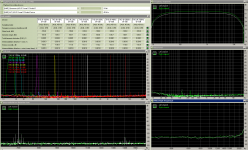
This is my definite favourite : 4 DAC(Iout=16mA p-p) PCM1796 @ R=10 Om + ina103kp:Круто:

nice surprise: ура:
nice surprise: ура:
Attachments
-
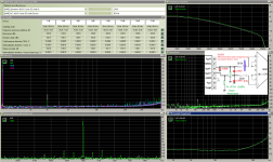 THD @96kHz @ 20 Om @ 3Cf_100nF.png108 KB · Views: 284
 -
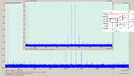 imd13_14 @48kHz @ 20 Om @ 3Cf_100nF.png209 KB · Views: 278
 -
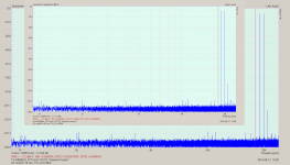
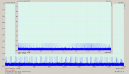 J-test @48kHz @ 20 Om @ 3Cf_100nF.png159.3 KB · Views: 260
 -
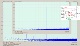 -30dB @48kHz @ 20 Om @ 3Cf_100nF.png304.6 KB · Views: 250
 -
 -6dB @ dF @48kHz @ 20 Om @ 3Cf_100nF.png66.1 KB · Views: 248
 -
 imd19_20 @48kHz @ 20 Om @ 3Cf_100nF.png201.6 KB · Views: 99
Last edited:
I use a ESS9018 K2M dac with tipical datasheet output. What components and values i should use in order to gain this effect discussed here ?
My DAC has more sources than PCM179x described in the first page (2xdigital and 3xanalog), should install supercapacitors to all of them ? Now are decoupled with 1uf||0,1uf ceramic caps.
Thanks!
My DAC has more sources than PCM179x described in the first page (2xdigital and 3xanalog), should install supercapacitors to all of them ? Now are decoupled with 1uf||0,1uf ceramic caps.
Thanks!
An externally hosted image should be here but it was not working when we last tested it.
Last edited:
My suggestion is to use large capacities for all power rails decoupling in analogue processing stages.
Another suggestion is to have a reference for the I/V stage a more stable zero/GND, instead that divider powered from AVCC.
Else please examine the suggestions in the beginning of the thread, to find that configuration may fit for you. Mainly the cap should be placed in between DAC`s outputs (here L+/L-).
Are really necessary all that filtering cells after the AC coupling caps? Yah, maybe theoretically... I would want to get rid of that. Just try it without.
Last edited:
So, Joe, you now have all your expenses covered to get a good set of measurements and ears-only listening tests. Are you ready to go?
My suggestion is to use large capacities for all power rails decoupling in analogue processing stages.
Will do.
Another suggestion is to have a reference for the I/V stage a more stable zero/GND, instead that divider powered from AVCC.
On my limited theoretical knowledge i unterstand will be better to connect this point to GND instead of this divider?
Else please examine the suggestions in the beginning of the thread, to find that configuration may fit for you. Mainly the cap should be placed in between DAC`s outputs (here L+/L-).
Are really necessary all that filtering cells after the AC coupling caps? Yah, maybe theoretically... I would want to get rid of that. Just try it without.
This filtering is for XLR output and i dont plan to use it.
Thanks for help!
The filter cells on XLR (your circuit) it load however the I/V output (in HF), and may affect the unbalanced output too. I may disconnect it anyway... removing the XLR AC coupling caps.
You should try to connect that point to GND, but this it may affect the DC setup for the whole circuit. You should experiment to find the right way to do it. If it works just to ground that point, then use it so. Else you should find the right configuration where the reference should be (better) zero volt,
You should try to connect that point to GND, but this it may affect the DC setup for the whole circuit. You should experiment to find the right way to do it. If it works just to ground that point, then use it so. Else you should find the right configuration where the reference should be (better) zero volt,
Last edited:
- Status
- Not open for further replies.
- Home
- Source & Line
- Digital Source
- Practical Implementations of Alternative Post-DAC Filtering