Hello Marc,
Great design, very informative 🙂.
I like the design very much.
paciently awaiting the finished design.
Many thanks,
Savu Silviu
Great design, very informative 🙂.
I like the design very much.
paciently awaiting the finished design.
Many thanks,
Savu Silviu
Wont be long, I unfortenatly went over the top on Sunday with the british Grand Prix and World Cup final, involving a few to many Carlsberg Special Brews and a Fish Curry for supper!
I have replaced the Wurth SMD output Inductor with the T106 core.
I have replaced the Wurth SMD output Inductor with the T106 core.
Hello😀
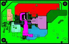
I'm happy to say after a couple of days of trying different minor changes to get the -12V supply in and optomise things a little:
I present for your critique the following layout. There are more vias to add to stitch the copper pours together, and the pours require the corners filleting. Keeping everything square just makes it easier to move things if you require any changes.
I can relax a bit know as all that is left is some minor tidying up, sorry it took so long, but I didn't wanto compromise the layout by rushing and havn't had that much spare time recently. I've got a holiday coming upp soon so for fun I want to do a double sided, 4 layer version. But first we will get this one sorted.
Having Fun
Marc
Attachments
Hello Marc,
Excellent job as always.
I have one month of vacation so if you finish the design in this period I will certainly take a try in building it.
Best regards,
savu silviu
Excellent job as always.
I have one month of vacation so if you finish the design in this period I will certainly take a try in building it.
Best regards,
savu silviu
Hi Savu,
There is some tidying up to do of the copper pours and more vias to add. I could do with you checking it over to make shure I havn't made any silly mistakes.
I finish work on friday for 2 weeks, the first week I'm off camping, the second week I'm just going to be sat at home. So I'll have a go at a double sided placement for fun.
I'll tidy things up over the next couple of days and post gerbers etc before I go on holiday.
Marc
Hi guys, I trust you are both enjoying your holidays. I am still researching for designs for use in a powered monitor speaker, but thinking this here is the one. I look forward to seeing the final layout, great work so far chaps!!
It looks very nice but I'm wondering why the output of LM311 is connected to Vcc+ and the GND pin is connected to base of QB3. Is it on purpose or there is a mistake in the schematic?
Who is doing prototype boards?
Mark
Who is doing prototype boards?
Mark
Hello Markus ...
the schematic is made like this on purpose.
it is not my schematic.
good question about the prototipe boards.
i will try to make them at home and if i fail i will contact a company that can make them.
regards,
savu
the schematic is made like this on purpose.
it is not my schematic.
good question about the prototipe boards.
i will try to make them at home and if i fail i will contact a company that can make them.
regards,
savu
I swapped the pins on the lm311 and boosted the performance quite a bit so i'd say its an error in the schematic, the author dident think straight when he came up with the design.
Even the phase lead network is incorrect, and theres no passive pole to correct the gain below the corner frequency of the output filter.
Even the phase lead network is incorrect, and theres no passive pole to correct the gain below the corner frequency of the output filter.
I have wondered about the LM311, it as always looked strange to me. Could you post your changes so that we can look at it. I do belive the circuit as is works, but if Savu thinks these changes would be benefitial it wouldn't take long to incorporate them.

I am using right now the original version with trough hole parts with the original pcb at 30V +/-.
it sounds good at 225Khz ...
but it misses dynamics on flac files.
have to test it to the limit but none of my friends will borrow a 1kw woofer for tests after they heard that i want to test this amp. 🙁
so i have to find a big woofer to test it to the limit.
regards,
savu
it sounds good at 225Khz ...
but it misses dynamics on flac files.
have to test it to the limit but none of my friends will borrow a 1kw woofer for tests after they heard that i want to test this amp. 🙁
so i have to find a big woofer to test it to the limit.
regards,
savu
- Status
- Not open for further replies.
- Home
- Amplifiers
- Class D
- PQFN 5X6mm Packaged N channel Power Mosfet in ClassD ...