I have a PPI 2075AM on the bench, nothing is shorted as far as large devices on heat sink. Upon applying power to remote, there is NO IDLE and amplifier’s power supply doesn’t power up.
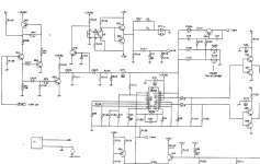
I am using the partial schematic provided by Perry in another thread, seems pretty similar. Q65 which is a MPSA56 and has is 121mv on collector. I have to inject 14vdc to the Q65’s collector pin in order to get amplifier to actually power up and 3525 to produce outputs on pins 11 & 14. Below are some reading if needed.
I am using 14.4vdc.
3525
1) 2.56v
2) 4.56v
3) 0.017v
4) 0.033v
5) 2.04v
6) 3.67v
7) 2v
8) 4.83v
9) 5.96v
10) 0
11) 0.014v
12) 0
13) 0.121 (this is the 121mv from Q65’s Collector pin)
14) 0.014v
15) 14.24v
16) 5.1v
Q65 MPS56
E) 14.4v B) 14.2v C) 0.121
I tested several 06/56 in that circuit and tested good, no leaks; confused as why Q65’s collector pin is not 14v.
This amplifier was damaged when the remote wire touched ground, in case that helps. Thanks for any input or advice.
Post a link to the diagram you found.
The base of Q65 isn't being pulled down enough to make it conduct.
The base of Q65 isn't being pulled down enough to make it conduct.
Q64
E) 0.00
B) 0.744
C) 0.008
Remote is 14.4v goes to 2.2k resistor (in network package) then to base of Q64.
I am also not 100% certain I have Q65 correct (as far as location), as there is another PNP near by that also has B+ going to its Emitter this reads E)14.4v B)13.7v C)14.4v but this can’t be Q65 because of the collector not being tied to 13. Pin 13 and 15 not tied on this amp like it shows on schematic hence why I was a bit confused.
Last edited:
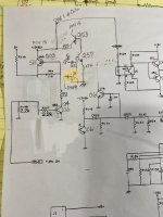
I drew up from what I had on my amp. Hope this makes more sense, but issue remains on (Q53 on my board) which has no voltage on Collector which goes to pin 13 of 3525. What is marked in yellow is an added factory revision seen on this model before, wondering if that may be the issue since that revision is tied to pin 9 of 3525 which is pretty high at 5.96v.
Attachments
If you already replaced this transistor, short it from collector to emitter. Does the amp power up?
I removed it and tested good, I replaced it with new and same issue.
With collector shorted to emitter the amplifier does power up.
With collector shorted to emitter the amplifier does power up.
I have -/+27.5 rails and -/+15v regardless of B+ voltage (12-14.4v remain the same), same with 5.1 Vreg. Idle at 400ma.
I don't know what that mod does.
What is the DCV on pin 9 of the 3525 when you adjust the 12v input as far as you can and the amp remaining on?
What is the DCV on pin 9 of the 3525 when you adjust the 12v input as far as you can and the amp remaining on?
- Home
- General Interest
- Car Audio
- PPI remote circuit turn-on help.