Working on this amp, right channel has +19Vdc on it and the left has -17Vdc. The left channel has the top part clipped off. The right channel has a signal riding on a dc level.
Reading other threads I found a schematic for the ceramic boards, what should the signal coming into pin 3 and 4 be.
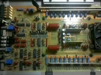
Attached is a photo of the pc board. Are the drivers Q9, Q10 on the ceramic board?
Reading other threads I found a schematic for the ceramic boards, what should the signal coming into pin 3 and 4 be.
Attached is a photo of the pc board. Are the drivers Q9, Q10 on the ceramic board?
Attachments
Measure the voltage again but this time, place the black probe on one of the non-bridging speaker terminals.
The signal on pins 3 and 4 should be audio with essentially no DC.
Do you have the proper supply voltage on both power supply pins of the op-amps?
Do you have the proper supply voltage on both power supply pins of the driver board?
Do you read 100 ohms for each placement (A and B) on the following image?
http://www.bcae1.com/temp/ppidriverboardresistoroverlay01.swf
+20Vdc on right channel
-4Vdc on the left
L+ to R- is the bridged terminals I believe.
+-13 on the op-amps
+-60 on pins 1 and 15
The right channel has no 100 ohm readings and the left channel "B" reads 100 ohms only.
-4Vdc on the left
L+ to R- is the bridged terminals I believe.
+-13 on the op-amps
+-60 on pins 1 and 15
The right channel has no 100 ohm readings and the left channel "B" reads 100 ohms only.
Install a 100 ohm resistor as is shown for the open resistor.
You can determine which ones are the non-bridging terminals by finding the ones that read 0 ohms between them.
You can determine which ones are the non-bridging terminals by finding the ones that read 0 ohms between them.
The left channel is functioning now.
The right channel is sitting with 55Vdc on it and the ceramic module is getting extremely hot. This channel has the signal riding on a dc level on pins 3 and 4 also.
The right channel is sitting with 55Vdc on it and the ceramic module is getting extremely hot. This channel has the signal riding on a dc level on pins 3 and 4 also.
Check the small predriver transistor on the top right corner of the driver board. Is it shorted or leaking?
Compare to the other board if you can't tell if it's leaking.
Have you checked the large transistors on the driver board?
Compare to the other board if you can't tell if it's leaking.
Have you checked the large transistors on the driver board?
Looking at the pic you sent, the two directly above the large transistors? Comparing between the two boards, 3 of 4 measure shorted from B-E(two pins on same side). I could have the probes touching though.
It depends on the condition of the board. Sometimes when heat is applied to these boards, the traces contract and open. You don't want heat anywhere that it doesn't need to be. I'd suggest using a soldering iron. You can use solder paste if you'd like.
Would a 1206 pkg resistor work for the 100 ohm I need to replace?
Also the part marked "YV" sot23 package, is that a zener or A92?
Also the part marked "YV" sot23 package, is that a zener or A92?
Last edited:
You can't install an SMD resistor in place of the original. The only viable options (in my opinion) are to use a leaded resistor and connect it as shown in the image or to replace the board.
As a side note, if the 100 ohm resistor didn't open 100% (they rarely do), you need to remove the transistor and cut the resistor through completely. If you don't, it could cause strange problems later.
MMBTA92
As a side note, if the 100 ohm resistor didn't open 100% (they rarely do), you need to remove the transistor and cut the resistor through completely. If you don't, it could cause strange problems later.
MMBTA92
I used a leaded resistor like your diagram. I understand the resistor couldn't go in place of the carbon resistor.
How warm do these boards get? These are getting hot to the touch after a few minutes.
How warm do these boards get? These are getting hot to the touch after a few minutes.
Alright, got a little nervous didn't want something to burn up.
I see the plugs are available from a seller on ebay, but is there a cross to the existing ones from Molex or wiedmuller or phoenix?
I see the plugs are available from a seller on ebay, but is there a cross to the existing ones from Molex or wiedmuller or phoenix?
A few of the 2sa1303's are bad, does the FJA4213 or FJL4215 work. I believe the "L" is just fully encapsulated.
I would expect the FJA to work but I've never tried them in a PPI amp. The FJL is in the TO-264 case (larger).
- Status
- Not open for further replies.
- Home
- General Interest
- Car Audio
- PPI PCX-2400