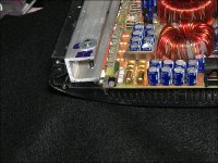
I have a pcx-1500 i picked up recently that had some burning right behind the input RCA's, where there is a pair of resistors on the rca grounds. and the resistor bands are different on each? I want to know the value of these resistors to replace them.
I also have a PCX-2200, and In the user manual for both amps it says its a 47ohm resistor in the "noise reduction topology" when i measure the resistors on the 2200 i get 47 ohm and on the 1500 I get ~44k ohm.
Should it be 47 or 47k??
I also have a PCX-2200, and In the user manual for both amps it says its a 47ohm resistor in the "noise reduction topology" when i measure the resistors on the 2200 i get 47 ohm and on the 1500 I get ~44k ohm.
Should it be 47 or 47k??
Those resistors commonly burn when a speaker wire is shorted to ground.
They're supposed to be 47 ohms. They're connected between the RCA shield and the secondary ground.
They're supposed to be 47 ohms. They're connected between the RCA shield and the secondary ground.
Thank you for the prompt response! What wattage resistor should i replace them with? the 47k's currently in there appear to be 3 watt? But the 2200's are much smaller and also show light heat stress.
Also I have another question concerning the PCX-2200
The Right channel will not play. The left works fine. When I measured the output from the Right channel I measured a steady1.9v DC and only slight AC voltage.
When measuring the good channel I get a max of ~.05v DC. When bridged, sound comes out but very distorted (more so on low freq.)
The 47 ohm resistors, under normal operating conditions, will never see more than a fraction of 1 watt. A 1/8w would probably survive forever. The larger resistors survive for short periods of time when a speaker wire shorts to ground. You can use 1w or larger. I'd suggest installing them so that the body of the resistor is at least 1/4" off of the board. This will protect the board if the resistor overheats.
Have you tried to adjust the DC offset for the defective channel?
Have you tried operating all of the switches and pots (externally accessible) through their entire range to see if the audio returned back to normal levels?
Do you have a scope?
Have you tried to adjust the DC offset for the defective channel?
Have you tried operating all of the switches and pots (externally accessible) through their entire range to see if the audio returned back to normal levels?
Do you have a scope?
BTW should i ethe resistors on the 1500 if it is working as is? When i got itchange, it had power but there was no sound but when i cleaned the board near the burnt reisitors it must have cleared up a short as it is working fine now. On these amps the rca jacks double as high level inputs ( up to 12v sens.) That might increase wattage?
I tried operating all switches to no avail, the gain crackles when adjusted.
I have not tried adjusting dc offset, this 2200 has to have the bottom on to clamp the transistors down. tho other 2200's I've seen have side clamps like my 1500 does.
Which way would I turn it? or just trial & err?
The positive DCV appears to come from R-?
I dont currently have a scope...
If the 1500 is working, I'd leave it as is. If you have to disassemble it to replace the resistors, you will need to remove and replace the heatsink compound.
If you do anything with the 2200 with the cover off, you need to make clamps to hold everything tight to the heatsink. Failure to clamp all components could lead to the amp failing. Have no more than a 15 amp fuse in the B+ line when making adjustment. The easiest clamps to make are probably using C-channel (below).
The 20k pots are the DC offset pots. Turn it slowly to see which way reduces the offset. The channel could have (probably has) other problems if you can't zero the offset.
Attachments
I didn't try adjusting offset yet as I haven't had time to make clamps.
But I think I may have found the problem?
http://www.bcae1.com/temp/ppidriverboardresistoroverlay01.swf
I tested all the transistors and couldnt find any bad components so i was trying to inspect closer to see if I could spot ANYthing and noticed hot spots by the driver card. I found this link for information and the test points on my Good channel both test points A&B~100 but Bad channel reads A~100 B-1950 what could I do about this?
You could connect an external 100 ohm resistor. This could allow you to see if the amp functions normally with the resistor. IT may not be a permanent solution without removing the transistor to destroy the original printed resistor. Sometimes the printed resistor can cause noise problems if not wiped out. Do this as a last resort only because simply removing the transistor could damage the driver board.
ok I tried soldering in an external 100 ohm 1watt resistor with some small wire leads and it didnt work, there was a change in the output now about half A.c. & half dc? (Half average voltage of other channel. What can I do about replacing the card? Or maybe a schematic? Would replacing the bf733/bf732 transistors work?
When you soldered to the board, did the solder pull away from the pads? You may need to use a high-power lighted magnifying glass to see it.
The only options for replacement boards are salvage from another amp or use an aftermarket board. The only aftermarket board I know of at this time would be from a guy in England. It's an SMD board and you have to populate the bare board.
Replacing them won't do any good if they're not defective. They have a tendency to develop bad solder connections.
- Status
- Not open for further replies.
- Home
- General Interest
- Car Audio
- PPI PCX-1500 input resistor value.