Gentelmen I have SB Audience BIANCO-18SW450 18" Subwoofer 2 nos would these drivers work in PPD if yes will be great cause i dont have space for 3cuft per driver in my room . Had got them for my OB DIY if you guys say do it will try them My Satellite are tang band 1808 sealed 30 litre
Yes, it is - I did such experimentsThe small opening works as low pass filter reducing output on high frequencies, including distortion, doesn't it? One could put such front panel/aperture to a closed box or reflex box woofer as well.
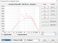
Thank you 👍Screenprint attached.
Last edited:
Mighty speakers! Of course, they will work in PPD, the main thing is that you have powerful enough amplifiers for them)))Gentelmen I have SB Audience BIANCO-18SW450 18" Subwoofer 2 nos would these drivers work in PPD if yes will be great cause i dont have space for 3cuft per driver in my room . Had got them for my OB DIY if you guys say do it will try them My Satellite are tang band 1808 sealed 30 litre

yes I have 2 nos in Hypex NC502MP OEM so I can use in BTL load each driver with each amp I had got these to power my peerless stw 350 but still lazy to make the boxMighty speakers! Of course, they will work in PPD, the main thing is that you have powerful enough amplifiers for them)))
Hi,Mighty speakers! Of course, they will work in PPD, the main thing is that you have powerful enough amplifiers for them)))
sorry to catch on to this line but thinking home application and comparing efficiency of big and small woofer it doesn't feel relevant advice. Its somewhat personal thing as all of my friends seem to think that big speakers need big amplifiers so felt I have to write it open here 🙂 Its counter intuitive but small woofers need the more powerful amplifiers, bigger woofers can do the same SPL with less powerful amplifier, or use the extra power to get extended bandwidth. Its a myth that big system would need big amplifier.
Of course one can feed more power to a big woofer with bigger voice coil and potentially get more SPL than a smaller woofer so in that sense its true, big amps can be used with big woofers to their maximum potential. Small woofer with small amp have far far less max SPL capability than big woofer with big amp so yeah, its good advice in that sense, much much more performance.
For home application everything is fine as long as there is enough performance. Usually big woofers with normal / small amplifier is fine, much better than small woofer with the same amplifier one already has. Coffee break over 🙂
Last edited:
1500 looks preferable for PPDwould a JBL GTI 1200 or 1500 car subwofer driver (12" or 15") work?
For those who decide to try the PPD, one important note: be sure to try to connect it in your system also in the antiphase option. This connection is especially relevant when using DML-type speaker systems.
Differing vent phase due to differing compression ratio?
If that was the case then the simulation model would have taken it into account, but the results at 100 Hz in Post #51 suggest that the phases are not being affected.
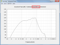
Front port output phase = 43.2463 deg
Rear port output phase = -136.8685 deg
Phase difference = Front phase - Rear phase = 43.2463 - (-136.8685) = 180.1148 deg
Yeah, typed it for preview/reminder to look deeper into it on the way to bed after another sleepless night only too late to see I'd posted it. 🙁
So there's little sidewall/ceiling/floor reflection, and the rear reflection off the wall is phase-delayed by ~2m becoming constructive ~28-140hz (any wavelength 1.2-6X the path length).
Increasing the effective acoustic path length between the two outputs by utilising a rear reflection surface would certainly improve things, as shown in the attachment, but presumably there are no reflections occurring under the conditions below, and the measured performance is reported to be even better.
On the street, all measurements remain valid and look even better than indoors.
Attachments
What do you mean, getting?  In years, just so-so at 76 based on my long lived relatives, but then I saw all those famous folks that were around me or younger checking out. 🙁
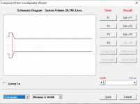
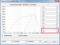
In years, just so-so at 76 based on my long lived relatives, but then I saw all those famous folks that were around me or younger checking out. 🙁Below is my simulation with increasing port spacing to one meterIncreasing the effective acoustic path length between the two outputs by utilising a rear reflection surface would certainly improve things,
Attachments


I'm poor in mathematics, so my thinking mostly follows just common sense and practical testing. Dipole radiation principle is simple but with asymmetrical constructions like this PPD, common sense will be in trouble. I don't know everything about ripole, but I see it as basic dipole, but sideways.
Excellent pages by John Kreskowsky http://musicanddesign.speakerdesign.net/tech.html
About front wall reflection http://musicanddesign.speakerdesign.net/Boundary_reflections.html In-room bass response below 100Hz is always mix of direct and reflected soundwaves! Taking measurements too close to a driver/baffle or a port is misleading, just a piece of a puzzle.
And question to David - what is the virtual mic distance and orientation in Hornresp sims? Is distance taken from driver's surface ( I suppose it is planar)
Off-axis behaviour tells much more about dipole systems than just on-axis. Eg. a tube (H) with different length of "pipes" will move nulling plane towards the longer pipe. And large conical driver will have it's nulling axis at around 80deg!
AKABAK etc. models are nice like here about cardioid with side vents https://www.audiosciencereview.com/...adiation-via-lateral-slots-like-d-d-8c.37863/
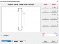
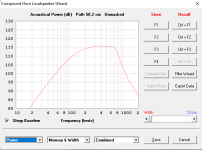
Below is my simulation with increasing port spacing to one meter
It is is not necessary extend the actual port length - just set the path length parameter value to the desired value.
Attachments
what is the virtual mic distance and orientation in Hornresp sims? Is distance taken from driver's surface
Because power response is being calculated, orientation of the system does not matter. The acoustic output power is assumed to radiate uniformly in all directions from a point source and the resulting pressure at the surface of a virtual 1 metre radius sphere, centred on the source, is used to calculate the SPL.
SPL values are adjusted accordingly if radiating into less than 4Pi free space.
See the post linked below for further details:
https://www.diyaudio.com/community/threads/hornresp.119854/page-523#post-6069923
Hi all,
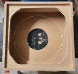
I cannot handle any simulation tools, I just think I am not smart enough, I have to build it ...
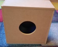
I did just build a PPD subwoofer using a Jensen JWS 300 CP subwoofer driver.
I ordered them some time ago to build such a Ripol:
https://www.diyaudio.com/community/threads/killer-dipole-bass-dirt-cheap.377255/#post-6800320
But I never built it, so I try this one now in a PPD subwoofer.
I measured the TSP for that woofer with LIMP:
Loudspeaker parameters:
Fs = 31.30 Hz
Re = 3.41 ohms[dc]
Le = 671.17 uH
L2 = 1670.11 uH
R2 = 28.27 ohms
Qt = 0.76
Qes = 0.87
Qms = 6.07
Mms = 107.11 grams
Rms = 3.487716 kg/s
Cms = 0.000241 m/N
Vas = 147.88 liters
Sd= 660.52 cm^2
Bl = 9.074043 Tm
ETA = 0.50 %
Lp(2.83V/1m) = 92.80 dB
Added Mass Method:
Added mass = 32.00 grams
Diameter= 29.00 cm
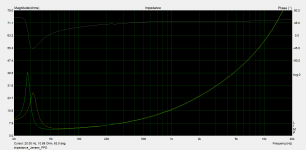
I measured the impedance of the driver alone (yellow) and in the box (green) with LIMP, just in the empty box.
Let's see if I can get more measurements, it's been a long time using Arta.
Ulf
I cannot handle any simulation tools, I just think I am not smart enough, I have to build it ...
I did just build a PPD subwoofer using a Jensen JWS 300 CP subwoofer driver.
I ordered them some time ago to build such a Ripol:
https://www.diyaudio.com/community/threads/killer-dipole-bass-dirt-cheap.377255/#post-6800320
But I never built it, so I try this one now in a PPD subwoofer.
I measured the TSP for that woofer with LIMP:
Loudspeaker parameters:
Fs = 31.30 Hz
Re = 3.41 ohms[dc]
Le = 671.17 uH
L2 = 1670.11 uH
R2 = 28.27 ohms
Qt = 0.76
Qes = 0.87
Qms = 6.07
Mms = 107.11 grams
Rms = 3.487716 kg/s
Cms = 0.000241 m/N
Vas = 147.88 liters
Sd= 660.52 cm^2
Bl = 9.074043 Tm
ETA = 0.50 %
Lp(2.83V/1m) = 92.80 dB
Added Mass Method:
Added mass = 32.00 grams
Diameter= 29.00 cm
I measured the impedance of the driver alone (yellow) and in the box (green) with LIMP, just in the empty box.
Let's see if I can get more measurements, it's been a long time using Arta.
Ulf
Attachments

- Home
- Loudspeakers
- Subwoofers
- PPD subwoofer