Hi Y'all,
I made myself a sketch of the SWR 12D2, and turned the drawing around, to have a better starting point.
Now we'll have to know what changes can be made to make driver mounting possible through a front slot (one could make part of the side panels removable, and mount from there?).
Regards,
You are right, the slot needs to be 8.375 wide minimum to fit second driver in. Cabinet will be 35.75 wide now. I wonder if that is too wide for the OP?
Hi again,
Just a quick suggestion that I think would work, and still give very similar acoustic results:
Regards,
Tb46,
That's very cool looking. It probably would work well and I can model it as soon as I get back to my computer. One thing to keep in mind is that the OP wants to add a small 7x8in exit duct to go through a car back seat. I wonder if the larger expansion suddenly necking down will work as well. Easy enough to test in the model. Thanks for helping.
X
Last edited:
Hi again,
Just a quick suggestion that I think would work, and still give very similar acoustic results:
Regards,
Tb46
i like your suggestion but i have two question to ask. Please take a look at the attach picture.

You are right, the slot needs to be 8.375 wide minimum to fit second driver in. Cabinet will be 35.75 wide now. I wonder if that is too wide for the OP?
xrk,
The 35.75" wide box can fit in my trunk, but would it affect the duct.
Last edited:
Hi lawbiding,
I added the dimensions you asked for into the drawing. I just use the software to put in the dimensions, so some numbers end up being a bit strange, but it's not necessary to get this to the last thousands. I also checked the cross-sectional area behind the driver, it is just a little bigger than before (You could use the added area/volume to add a brace @ the input to the duct, e.g.: a 2x4 w/ a rounded corner. I put it in the drawing in dashed line.)) The duct is the same length I measured in the other drawing.
Wait for xrk971's AkAbak simulation to see if anything has to be modified.
Regards,
Attachments
xrk,
The 35.75" wide box can fit in my trunk, but would it affect the duct.
It should still work well. I wouldn't worry about too much - that's not a big change.
Hi lawbiding,
I added the dimensions you asked for into the drawing. I just use the software to put in the dimensions, so some numbers end up being a bit strange, but it's not necessary to get this to the last thousands. I also checked the cross-sectional area behind the driver, it is just a little bigger than before (You could use the added area/volume to add a brace @ the input to the duct, e.g.: a 2x4 w/ a rounded corner. I put it in the drawing in dashed line.)) The duct is the same length I measured in the other drawing.
Wait for xrk971's AkAbak simulation to see if anything has to be modified.
Regards,
Tb46
Enough Thanks for the drawing.
It should still work well. I wouldn't worry about too much - that's not a big change.
xrk971
I really appreciate everything you and Tb46 have done with this project.
I am going to look over the drawing to make sure i understand everything. I might still have few question to ask. LOL
Thanks
Last edited:
xrk,
The 35.75" wide box can fit in my trunk, but would it affect the duct.
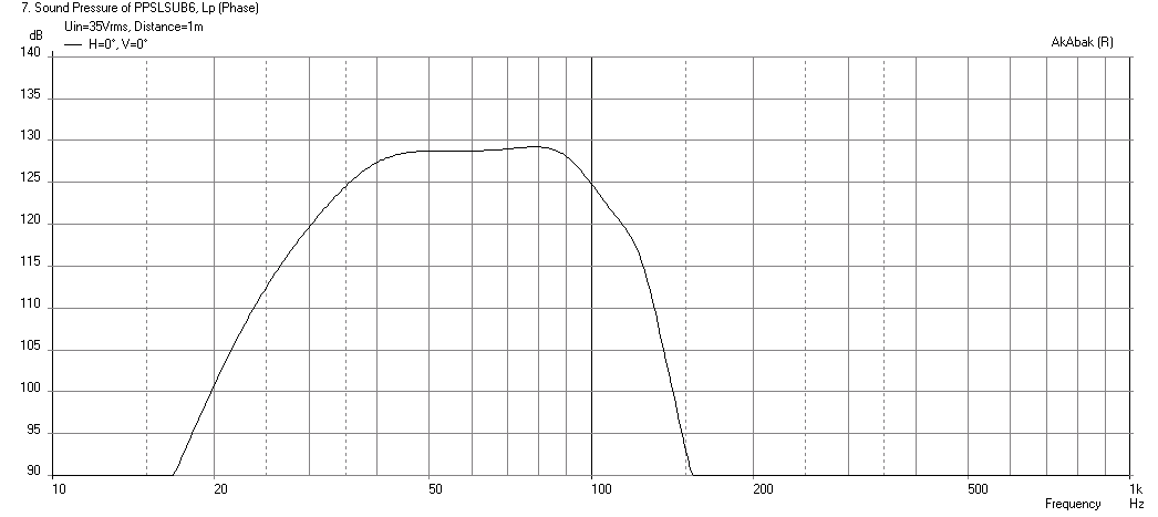
Here is the response with an 8.5in wide x 13.5in tall slot chamber. This should be big enough for you to slip the two drivers in during the installation process. The bass extension is now 36Hz at -3dB with an output of 128dB at 35volts. Seems like it should work just fine.
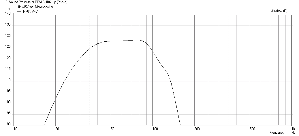
And here is the output with just the angled waveguide, no seatback duct at 35v (less bass extension but can extend higher up to 150Hz), shown with 120Hz LPF:

Attachments


Last edited:
Hi lawbiding,
I added the dimensions you asked for into the drawing. I just use the software to put in the dimensions, so some numbers end up being a bit strange, but it's not necessary to get this to the last thousands. I also checked the cross-sectional area behind the driver, it is just a little bigger than before (You could use the added area/volume to add a brace @ the input to the duct, e.g.: a 2x4 w/ a rounded corner. I put it in the drawing in dashed line.)) The duct is the same length I measured in the other drawing.
Wait for xrk971's AkAbak simulation to see if anything has to be modified.
Regards,
Here is the predicted response with the angled waveguide slot followed by the duct leading through the seats. Looks about the same, maybe a bit less SPL and bass extension is still around 36Hz at -3dB. This is for 35volts input:
I like how this makes it very easy to install the drivers because you can get to the mounting screws very easily. Nice work there Tb46!
Here is what it looks like without the 12in duct leading to the seats (and no LPF) - very wide bandwidth:
Attachments


Last edited:
Here is the with the angled waveguide slot followed by the duct leading through the seats. Looks about the same, maybe a bit less SPL and bass extension is still around 36Hz at -3dB. This is for 35volts input:
I like how this makes it very easy to install the drivers because you can get to the mounting screws very easily. Nice work there Tb46!
Here is what it looks like without the 12in duct leading to the seats (and no LPF) - very wide bandwidth:
xrk971
Thanks for the spl graph.Would it be ok to mount the drivers push pull in the angled waveguide slot design that Tb46 suggest?
What will be the predicted response when the box is stretch to 35.75'' or
36'' with the 12'' duct attach and detach to the box.
xrk971
Thanks for the spl graph.Would it be ok to mount the drivers push pull in the angled waveguide slot design that Tb46 suggest?
What will be the predicted response when the box is stretch to 35.75'' or
36'' with the 12'' duct attach and detach to the box.
Disregard this post 52. Sorry
Last edited:
xrk971 and TB46
Would it be ok to mount the drivers push pull in the angled waveguide Tb46 suggest and also in the 35.75" wide box.
Tb46,
Please take a look at the attach picture.

Thank you Sirs
Would it be ok to mount the drivers push pull in the angled waveguide Tb46 suggest and also in the 35.75" wide box.
Tb46,
Please take a look at the attach picture.
Thank you Sirs
It should be fine to mount push pull with magnet sticking out on one side. It may be tricky getting it to fit but as far as air flow goes, not a problem. You may get more magnet vent hole noise with drivers angles out - but if sitting behind behind car seat duct, not an issue.
Hi Y'all,
I'll attach a drawing revision showing the push-pull drivers, and the added dimensions. I would recommend to widen the front slot by about 1/2" for push-pull, and to build a quick trial mock-up to see if you can reach the mounting screws.
The AkAbak data looks quite good. 🙂
Regards,
I'll attach a drawing revision showing the push-pull drivers, and the added dimensions. I would recommend to widen the front slot by about 1/2" for push-pull, and to build a quick trial mock-up to see if you can reach the mounting screws.
The AkAbak data looks quite good. 🙂
Regards,
Attachments
Tb46Hi Y'all,
I'll attach a drawing revision showing the push-pull drivers, and the added dimensions. I would recommend to widen the front slot by about 1/2" for push-pull, and to build a quick trial mock-up to see if you can reach the mounting screws.
The AkAbak data looks quite good. 🙂
Regards,
Thanks for the drawing. I don't have any problem making the front slot 1/2'' wider,wouldn't that change some of the measurements and layout.
I like the look of the push pull.
Last edited:
That driver has some really big movements as xmax is 20mm. Xmax physical limit is even higher. Just make sure you have enough room so that the cone doesn't end up punching the rear magnet of the reversed one. Thanks for the drawings Tb46 - the look is really cool and I hope this gets built.
That driver has some really big movements as xmax is 20mm. Xmax physical limit is even higher. Just make sure you have enough room so that the cone doesn't end up punching the rear magnet of the reversed one. Thanks for the drawings Tb46 - the look is really cool and I hope this gets built.
Xrk971
Believe me when I said, I am going to build it.
I dont like to waste people time when there are helping me.lol
Hi lawbiding,
Post #57: "...wouldn't that change some of the measurements..."
Yes, it would. There are a number of ways of doing this, the simplest is to just widen the box by 1/2". Push left and right box away from the center line by 1/4" each. I like that method. But you'll still have to make sure that you can mount the drivers, i.e.: make a simple mockup.
My driver drawing is not a drawing of the actual item. The outside is an overlay of the factory drawing to the factory dimensions. I'm guessing at the position and shape of the cone. That's only a starting point, you'll have to verify that it fits.
Regards,
- Home
- Loudspeakers
- Subwoofers
- PP Slot Loaded Sub with Alpine SWR 12D2