xrk971 what will happen if the duct/port is cut to 12''.
Can you explain the bracing in the box a little clearer.
Can you give me the measurements for the line in the attach picture.
View attachment 448467
Thanks
I will get you a bettwr sketch soon. Basically for the brace in the vent channels use 3/4in plywood cut into strips 1.00in thick - use two of them in the channels. The channel length needs to be 24in long.
I will get you a bettwr sketch soon. Basically for the brace in the vent channels use 3/4in plywood cut into strips 1.00in thick - use two of them in the channels. The channel length needs to be 24in long.
xrk971 i am talking the 16'' long duct what . what will be the box output if the 16'' long duct is cut to 12''

xrk971 i am talking the 16'' long duct what . what will be the box output if the 16'' long duct is cut to 12''
View attachment 448501
Not much of a difference, all I did was change length to 12in from previous case:
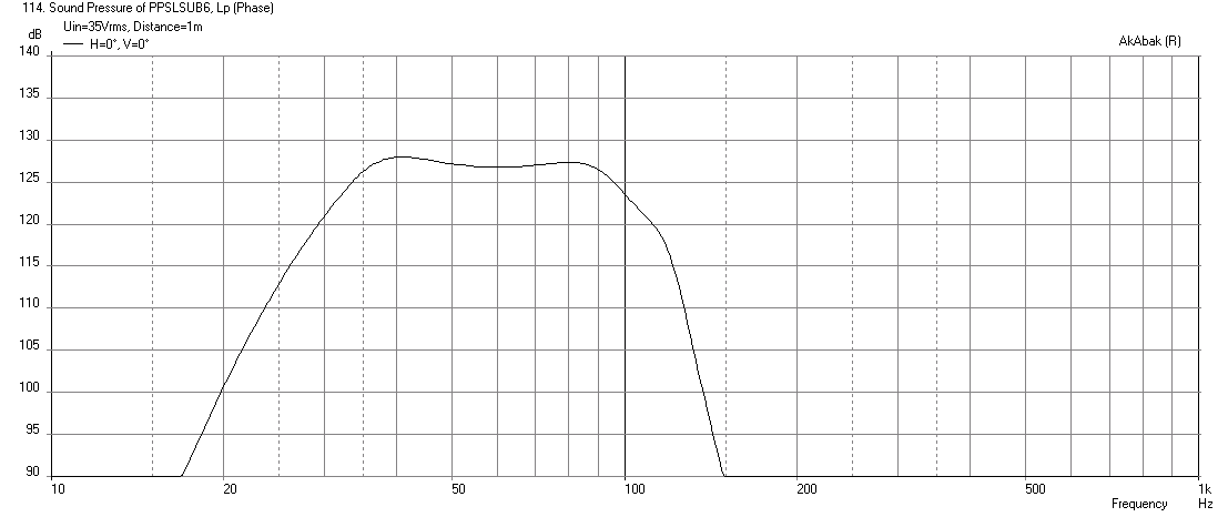
Here is the 16in long duct case for easy reference:
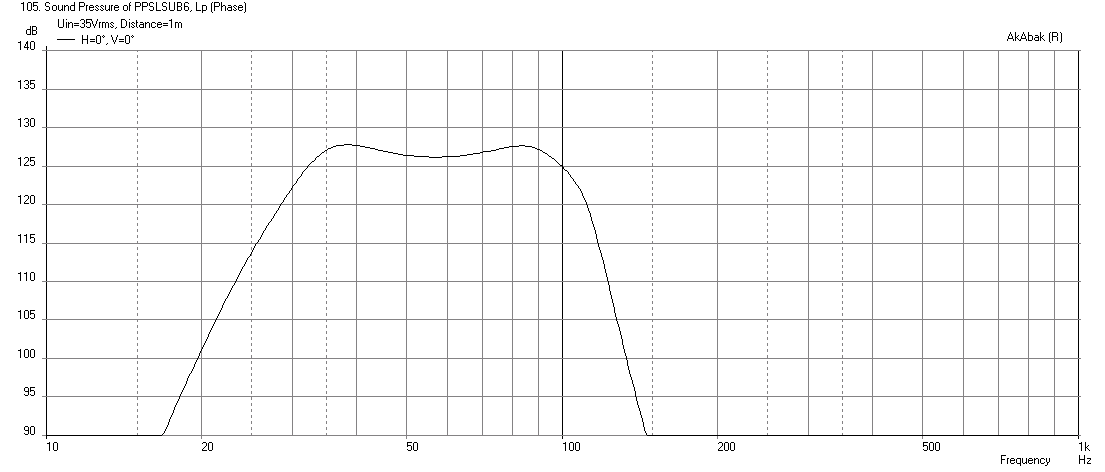
The 12in duct actually has less of a saddle and is flatter, slightly higher output and a tad reduced bass extension. In fact, you could make the extension duct in several sizes for tunability. If you can go with 12in long, that is preferred.
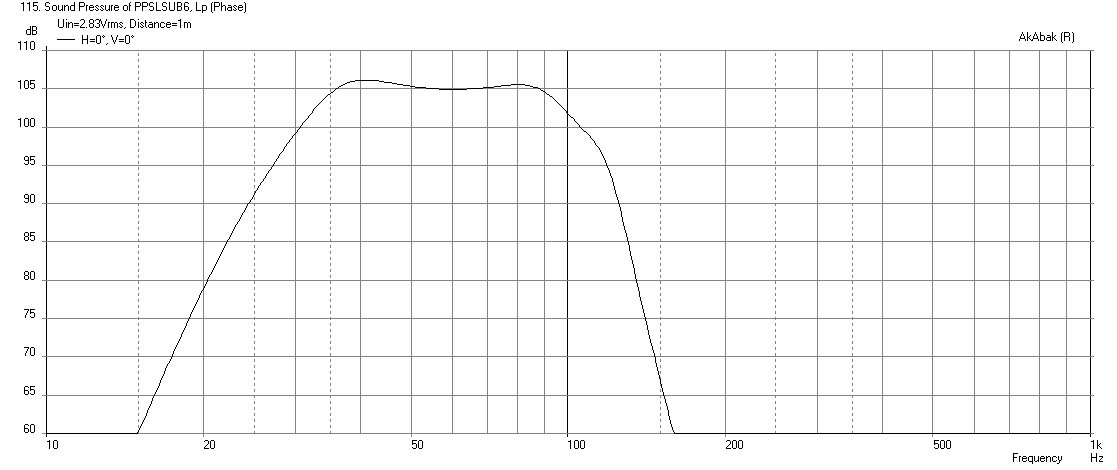
For reference, here is the result at 2.83volts for 12in long extension duct (105dB sensitive with -3dB point at 32.3Hz):
Attachments

Last edited:
Not much of a difference, all I did was change length to 12in from previous case:
Here is the 16in long duct case for easy reference:
The 12in duct actually has less of a saddle and is flatter, slightly higher output and a tad reduced bass extension. In fact, you could make the extension duct in several sizes for tunability. If you can go with 12in long, that is preferred.
thanks
Are you going to build it?
Yes sir i am going to build it on my vacation which is coming up. Thanksgiving week.
Remember the measurement I ask you for. I want to build this box the T
THanks
Last edited:
xrk971 what will happen if the duct/port is cut to 12''.
Can you explain the bracing in the box a little clearer.
Can you give me the measurements for the line in the attach picture.
View attachment 448467
Thanks
The vent panels are 0.5in thick and 12in long ea. The main back panel has to accommodate a 12in long chamber plus 4x0.75in panels for driver cutouts and ends, my calc shows 32.5in long. The end panel has to accommodate the 12.25in depth, 2x0.5in vent panels, 2x1.0in vent gaps, and 0.75in rear panel, my calc shows 16.75in long. The deflector triangle is not critical but about 5in wide x 2in tall should work.
Attachments
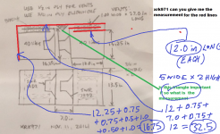
The vent panels are 0.5in thick and 12in long ea. The main back panel has to accommodate a 12in long chamber plus 4x0.75in panels for driver cutouts and ends, my calc shows 32.5in long. The end panel has to accommodate the 12.25in depth, 2x0.5in vent panels, 2x1.0in vent gaps, and 0.75in rear panel, my calc shows 16.75in long. The deflector triangle is not critical but about 5in wide x 2in tall should work.
Xrk971 maybe I am wrong but i think the measurements are bit off.
Xrk971 maybe I am wrong but i think the measurements are bit off.
Would you care to elaborate? The design I have provided in terms of the chamber volume, vent dimensions, slot dimensions, and extended duct dimensions are all that are needed to build this box. I have provided a rough dimensioned sketch but it is up to the builder to calculate final cut dimensions based on box volume and driver physical size, and on actual material thickness like 3/4in ply is actually 0.709in, etc. You can be creative and make triangular back chambers etc - just maintain chamber volume and ensure vent dimensions (CSA and length) and slot dimensions (CSA and length). Sometimes, I am lucky and Tb46 will make a nice CAD blueprint based on what I have given above. You should be able to figure it out, unless it is an error with getting driver to fit through the 7in wide slot.
Last edited:
Would you care to elaborate? The design I have provided in terms of the chamber volume, vent dimensions, slot dimensions, and extended duct dimensions are all that are needed to build this box. I have provided a rough dimensioned sketch but it is up to the builder to calculate final cut dimensions based on box volume and driver physical size, and on actual material thickness like 3/4in ply is actually 0.709in, etc. You can be creative and make triangular back chambers etc - just maintain chamber volume and ensure vent dimensions (CSA and length) and slot dimensions (CSA and length). Sometimes, I am lucky and Tb46 will make a nice CAD blueprint based on what I have given above. You should be able to figure it out, unless it is an error with getting driver to fit through the 7in wide slot.
The external of the when I calculated the measurements is 34×15×19.75.
I might be wrong but I am still checking.
The external of the when I calculated the measurements is 34×15×19.75.
i also cant get the slot port measurement to fit in the box, I might be wrong but I am still checking.
View attachment 448588
i also cant get the slot port measurement to fit in the box, I might be wrong but I am still checking.
View attachment 448588
xrk971 can you take a look at these two layout and let me if any of them is correct. I still cant figure out the measurements for the slot port section of the plan.


Thanks
Thanks
I was up early and put this together.
xrk971 this is the measurements that i calculate. 34x15x19.75
The slot port i did not calculate because i think something i missing.

xrk971 this is the measurements that i calculate. 34x15x19.75
The slot port i did not calculate because i think something i missing.
Hi Y'all,
This is what I came up with:
Regards,
Tb46,
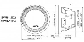
Thanks - looks great. I knew you would come through! 🙂 I did not realize the drivers are that deep - doesn't look like there is enough room to install them. I could have sworn the spec sheet said 6.375 in deep from flange to back. So I made it 7in wide. Did you get a different measurement? What is min slot width to fit drivers as push pull?
Cheers,
X
Edit: I think you have the 15.25 and the 13.5 dims flipped. The slot (and cabinet) is 13.5in high when viewed from slot opening. The depth of cabinet is 15.25in.
Last edited:
Hi X,
Please, note that I inserted a different Alpine model, as I noted in the drawing. I haven't had the time to draw the SWR12D2 yet. Also, still looking for the data. I'll take a look at switching the height and depth.
Regards,
P.S.: I'm adding the picture of the SWR 12D2, note that the 6-3/8" does not include the mounting flange.
Attachments
Last edited:
The specs are here
http://support.alpine-usa.com/products/documents/OM_SWR-10D2_4_12D2_4.pdf
The bezel is 1in thick so looks like slot needs to be 7.375min. Make 7.5in wide then for clearance then. That extra half in should not affect tuning or performance much. Overall length of box is now 34.5in.
http://support.alpine-usa.com/products/documents/OM_SWR-10D2_4_12D2_4.pdf
The bezel is 1in thick so looks like slot needs to be 7.375min. Make 7.5in wide then for clearance then. That extra half in should not affect tuning or performance much. Overall length of box is now 34.5in.
Last edited:
Hi X,
I think you'll need to add the flange twice, or mount one speaker into a recess. The second speaker will be installed after the first one is already in the box. Would that still work in Akabak?
Regards,
I think you'll need to add the flange twice, or mount one speaker into a recess. The second speaker will be installed after the first one is already in the box. Would that still work in Akabak?
Regards,
Hi Y'all,
I made myself a sketch of the SWR 12D2, and turned the drawing around, to have a better starting point.
Now we'll have to know what changes can be made to make driver mounting possible through a front slot (one could make part of the side panels removable, and mount from there?).
Regards,
I made myself a sketch of the SWR 12D2, and turned the drawing around, to have a better starting point.
Now we'll have to know what changes can be made to make driver mounting possible through a front slot (one could make part of the side panels removable, and mount from there?).
Regards,
Attachments
- Home
- Loudspeakers
- Subwoofers
- PP Slot Loaded Sub with Alpine SWR 12D2