Screen regulators II
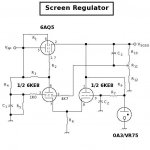
Same series pass device, but a different error amp topology. This design is also useful for making use of those odd ball 6X8s (triode/pentodes with common cathodes). This is an unbalanced differential type stage. The pentode half provides the voiltage gain, and the triode section provides the reference voltage. Since there is no current demand on the VR tube, its voltage stability is improved, and it can be operated at lower currents for less heating and drift. You can also employ an RC noise filter to remove some of the noise (even though VR tubes are quieter than Zeners, and the noise is less objectionable).
As for how they work: six of one; half dozen of the other. Both work just as well as any solid state design, and hold their output voltage to a variation of less than a volt over about a 40V variation in the unregulated DC. Both are dead quiet, showing no noise when o'scoping the output.
Attachments
Re: Re: Screen Regulators I
Yep, looks like someone was thinking along the same lines, though it looks like that schemo is using a helluvabig voltage differential across the series pass device. I opted for trioded 6AQ5s since I have a bunch, and the triode characteristics look pretty good for this particular purpose. Nice option for reducing AC hum, though both projects have pretty good ripple filtering, and AC hum is not a problem with either regulator shown here.
Both have been in service for over a year now, and are holding the voltage rock steady. I haven't had to tweak yet.
Wavebourn said:
Yep, looks like someone was thinking along the same lines, though it looks like that schemo is using a helluvabig voltage differential across the series pass device. I opted for trioded 6AQ5s since I have a bunch, and the triode characteristics look pretty good for this particular purpose. Nice option for reducing AC hum, though both projects have pretty good ripple filtering, and AC hum is not a problem with either regulator shown here.
Both have been in service for over a year now, and are holding the voltage rock steady. I haven't had to tweak yet.
Here is mine again, smart voltage regulator that instead of waiting for own filaments to heat up, is waiting for tubes that it powers to start drawing a current, then bias voltage increases, and since bias voltage is used as a reference B+ as well following it increases until positive feedback by current is shunted by a shunt regulator, now a negative feedback by voltage dominate, and you have a shunt bias regulator and a series B+ regulator in the single bottle, powered from the single transformer winding and a rectifier.
It is smarter than HP's. And outperforms it by all parameters. However, when HP-Agilent designed that famous tube voltmeters such solid state devices did not yet exist.

It is smarter than HP's. And outperforms it by all parameters. However, when HP-Agilent designed that famous tube voltmeters such solid state devices did not yet exist.
richwalters said:
Simplicity will do for screen regulation.
However those HV zeners with all the drift aren't for me.. Why the 75 ohm resistor ? .. You are relying on the 33uF for ripple rejection; the o/p could use a single 450V o/p cap.
My favourite would to use a 2nd mosfet and an ic to do the dirty regulation work. .
O.M.O.
richy
Hi Rich, thanks for your comments.
I agree about the driftiness of HV zeners, and they should probably be replaced by a string of VR tubes (two OA2 and one OB2 should do it). I could use a long string of the "magic" 6.2v zeners, which are drift-free, but it would require 66 of them!
Yves makes the point: "I use a resistor where you use zeners! Current being constant, voltage is constant too." It's probably an excellent solution. My CCS is in there just to drive the zeners under the conditions of varying B+, the amp being in Class AB1, but it could drive a resistor as he says. I think I'll try that.
The 75 ohm resistor is there to provide some protection to the MOSFET in case of a short.
Ripple rejection is provided by a previous pi filter with 50uf-5H-470uF (not shown), plus the 33uF cap - mainly to suppress zener noise, plus the 1.5Meg/2uF combination - which also gives a slow start for the screens.
The OP caps are in series because the ones I have are rated at 350v, otherwise I agree that a single cap of 450v rating would do.
- Status
- Not open for further replies.