I'm trying to solve a problem with 6550 Push-Pull amplifier which has toroidal ultralinear output transformer. The problem is that this amplifier is causing loud buzzing noise.
I have removed all the preamplifier stages and phase splitters, so only the 6550:s are right now used. The HT is filtered with CLC filter and it is nice sinewave so it is not causing the problem. Bias voltage is also looking nice.
It seems that the toroidal output transformer is somehow oscillating with the 6550s. I took this scope image from 6550 anode pin.
Any ideas how I should proceed to remove this oscillation? Right now I have 1k screen grid stopper and 4k7 grid stoppers.
I have removed all the preamplifier stages and phase splitters, so only the 6550:s are right now used. The HT is filtered with CLC filter and it is nice sinewave so it is not causing the problem. Bias voltage is also looking nice.
It seems that the toroidal output transformer is somehow oscillating with the 6550s. I took this scope image from 6550 anode pin.
An externally hosted image should be here but it was not working when we last tested it.
Any ideas how I should proceed to remove this oscillation? Right now I have 1k screen grid stopper and 4k7 grid stoppers.
Last edited:
What happens if you increase the grid negative bias? The transformer has no air gap and may be saturating.
What happens if you increase the grid negative bias? The transformer has no air gap and may be saturating.
No much difference. Of course if I put it so negative that current stops it becomes quiet. And the tubes seem to be matched. There's max 1mA difference between the idle currents so I assume the transformer is not saturated. The transformer specs days it should stand 200mA current and right now I'm using 80mA per tube.
I'm pretty sure the problem is that there's plenty of leak inductance in the transformer and it is causing this oscillation which will then induce spikes in secondary. And this is heard as buzzing noise.
I have seen other designs using a 220pF and 470R between the anode and the HT. Maybe that would stop it. 80mA is a bit hot for my taste but should be OK.
I have seen other designs using a 220pF and 470R between the anode and the HT. Maybe that would stop it. 80mA is a bit hot for my taste but should be OK.
I have one 100pF-1.5nF variable capacitor in insulated box. Maybe I should do some experiments with it and 470R resistor.
Toroidals OT often ring because of the interaction between their parasitics. Experimenting with a Zobel as discussed is probably your best option.
Shoog
Shoog
Good luck but don't be too heavy with the capacitor. It will cost you the higher frequency range. I would start with 220p and 470R, maybe 220R.
I think I used 1nF and 1k as a snubber. This was with EL34s driving a Sowter UL OPT. A poor quality OPT might need more snubbing.
Hmmmmm, to me your scope picture is showing a 100Hz frequency so most probably no oscillation - oscillation frequencies should be considerably higher.
Regards, Jürgen
Regards, Jürgen
^^ agreed, it looks like a 100Hz PSU induced buzz you might be hearing.
Superimposed on that is what looks like a higher frequency instability, that you may not be able to hear.
What I did find in Spice simulations as well as bench tests is a 180 deg phase shift that occurs between transformer UL and anode taps (in this case the Hammond 1628SEA at around 80kHz) leading to instability in a SE 6CA7 amplifier I built; the oscillation went away in triode and pentode mode.
A 220pF cap between G2 and the anode sorted that out to allow it to run in UL mode.
I tried with 560R resistor and 100pF-1.5nF variable capacitor in series. With HT and anode I didn't see any difference. Between anode and screen grid neither.
Between anode and grid I saw some difference, but I don't know if this is a solution.
In the scope screen above there's 100Hz HT ripple seen also in anode voltage, but this is not any problem. The real problem is those spikes, which are in reality damping oscillations with higher frequency. HT ripple is nice sine and those spikes are seen only in anode voltage. When I put 2kHz digital filtering to my oscilloscope and looked the transformer secondary, I can clearly see that those spikes in anode voltage are inducing audible spikes in output.
The noise is not like 100Hz hum, but buzzing sound. If I remove the 6550 tubes I cannot hear it. So it is not magnetically induced from mains transformer to the output. HT ripple is only about 500mV, so this should not be audible in P-P output stage.
Last edited:
1) Can you please post a schematic and picture of your build ?
2) Short input. Parasitics still present?
3) Please connect 8 ohm 50-100W wirewound resistor as dummy load, and feed your amp with 20 Hz sinewave and output power close to the max. Take a picture from oscilloscope and post here. Then do the same for 20 KHz.
Try to overload amp till heavy clipping and look what is happening, only clipping, or clipping with oscillation.
It will allow to determine if there is overall instability of the amp.
4) Try to disconnect global NFB, thus we can guess if this is instability due to NFB or input stage/phase splitter. Repeat test from p3.
5) Try to switch from UL to penthode mode, we need to understand if poor winding layout / low resonant frequency causes instability of output stage. Repeat test from p3.
Till you have done this we can only guess on coffee beans.
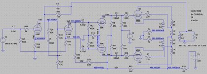
I have disconnected phase splitter and preamplifier and I'm just working with the P-P output stage to get this buzzing sound away. The circuit I'm working is looking like this (inductances are estimate):
V1 is HT with about 370V and 500mA ripple voltage. There's CLC-filter and the ripple is more or less sine. BIAS is about 33V with about 20mV ripple and there's CRC-filter.
An externally hosted image should be here but it was not working when we last tested it.
V1 is HT with about 370V and 500mA ripple voltage. There's CLC-filter and the ripple is more or less sine. BIAS is about 33V with about 20mV ripple and there's CRC-filter.
Last edited:
Please look at my Williamson simulation in LTSpice. It is actual schematic not only simulated, but also actually built and measured.
Your drawing either omits necessary details, either build prototype have errors.
1) Try to decrease grid leak resistors from 150K to 68K.
2) What is primary inductance. leakage inductance, and resonant frequency of your output transformer?
3) Have you tried to switch from UL to penthode or triode mode? Any changes?
4) Look for cold solder joints at grid pins of the tube sockets or elsewhere.
Sharing photo of your actual build may really help.
Attachments
Your scope might not have enough bandwidth to reveal the full magnitude of a severe RF parasitic oscillation. It could easily be up in the 100~200MHz region. Make sure your grid and screen stoppers are non-inductive resistor types and mounted with near-zero lead length at the tube sockets. It's important to dress anode and G2 wiring well away from grid wiring.
Is this a new build you are setting up, or has a fault occurred with a known good amplifier to cause this problem ?
Is the scope plot from the speaker output with a resistor load, and one connection taken to star ground?
Are the output valves balanced for cathode current.
Have you bypassed the grids to provide an AC short circuit, or increased the bias supply filter cap, to check if there is an influence?
The waveform shows power supply diode turn on and turn off points, with ringing at the turn-off. What parts are you using for the power supplies - it looks to me like bias supply noise.
That looks like power supply diode switching noise to me. Are you using Ultrafast Soft Recovery Diodes (that is UF4007 instead of 1N4007 etc.).
I have seen parasitic problems with Ultralinear Toroidal Output Trannies.
On one of Menno's VDV70/100 HiFi Amps. Quad of EL34. There were bursts of ultrasonics just after the peak of the sine wave I was testing with. At the time I guessed it was happening as one side of the push pull was either going into or coming out of cut off. That is at the Class A to B transition.
That amp had 150 Ohm screen stop resistors. Pushing them up to 1K fixed it.
The diode switch spike may be triggering the ultrasonic burst in this case.
Cheers,
Ian
Just for test purposes, try connecting the screens to their respective plates...just to remove the UL from the situation, for simplification...
makes sure your bias supply is well filtering and low in ripple...
Push-Pull toroidal transformer should not saturate... I usually use cut core and epoxy it back together with a fixed gap....
Are you 100% sure you do not have the phasing reversed on the screen wires ??
Chris
makes sure your bias supply is well filtering and low in ripple...
Push-Pull toroidal transformer should not saturate... I usually use cut core and epoxy it back together with a fixed gap....
Are you 100% sure you do not have the phasing reversed on the screen wires ??
Chris
I took a 200Mhz analog scope and started to measure different points. There's no any other oscillations which I hadn't seen with my digital scope. The spices were not seen in the bias- or HT-voltages.
Then I tried to remove 6550-tubes and measured the anode pin without the tubes. I was still able to see faint spike with the scope. So it seems that somehow the rectifier switching noise is magnetically coupled from mains transformer to output transformer. And this is inducing oscillation.
Then I tried to remove 6550-tubes and measured the anode pin without the tubes. I was still able to see faint spike with the scope. So it seems that somehow the rectifier switching noise is magnetically coupled from mains transformer to output transformer. And this is inducing oscillation.
- Status
- Not open for further replies.
- Home
- Amplifiers
- Tubes / Valves
- PP oscillation with toroid output transformer