Hi to all members!
My name is Gabriel, I have been a member since 2009 and lurked before that.
So far I have completed many projects to fruition thanks to others input, their encouragement, critics, and (hard) questionings!
I have been able to to gather from outside in literature missing pieces of calculations and theory to draw tube curves, calculate frequency response, cut off points, oscillation, and the hardest, amplifier gain and GNF loops, which I still don't understand, but I can measure it and listen to the difference it makes.
I have completed so far: many pre-amps (tube and SS), a hifi solid state 100 watt amp, a few 3-ways speakers (alnico, OB etc) and a 2-ways with passive radiator based on Usher drivers with XO simulators and real reactance curves measured in-room with my amplifier.
I acquired a true-RMS voltmeters, a variac, built a test station, dummy load, a dual channel THD analyzer and multiple channels SCOPES and gathered data stored in EXCEL charts, (some are lost now)
I built a few tube outputs from dacs, cd-players, but I am not a dac specialist and figuring oscillation and parasitic noise is too hard for me.
I modified 845 SET amplifier, and two solid state amplifiers.
I built a few PP amplifiers: kt77UL , el84 in triode, EL34 UL, Kt88 UL , Kt88 triode, Kt88 zero feedback, Kt88 LTP balanced input zero and with feedback, 6BL7 PPP, and a few more exotic dac tube outputs, and a Kt120 UL!!!
I have experience with a few types of transformers and many Hammond, Edcor, and high end ones.
I am lacking the experience with LTSpice and time!
The goal here is to post/develop an exotic circuit in LTSpice of a Kt120 PP amplifier which I designed and to bring it to perfection.
I set up years ago the OT to be a 5k low insertion loss high power 80W+ and high inductance design which will remain secret, let say it is similar to a Lundhal transformer. I wish other DIY members buy their choice of OTs and experiment and have the best circuit possible with tube respect to build their DIY amplifier. I have seen many designs and many commercial kits and built them, I want to build something unique which summarize the best knowledge in tube amplifier design and sound accuracy, beyond 'claims' and beyond 'exotic parts' and beyond 'this was good enough'
The philosophy here is to attain excellency by design choices which doesn't cost much as a DIY. I want us in the forum to get that extra listening pleasure that higher price amplifiers bring, not only by the choices of OT and feedback, but also by circuit design.
The amplifier would be a PP UL 70W 1% THD , B+ 600V, Bias servo 67.5 mA. GNF 10.5db or so. There is some margin and testing to do there, there should be a +/- 50 V in the B+ margin to build the amplifier, DIY's should be fine with using 40 Watts to 120 W OT , Bias would also be a choice, there should be room for experimenting by members while I build my own design.
The input tube would be by default a 6sn7gt in common cathode from TungSol or NOS of the highest fidelity, possibly using both sections as follower using the cathode part to take the signal out...
The driver tube would be overkill and easy to obtain like a LTP ECC99 and CCS EL822 (which required a tube and separate TX+PS), it could be also an alternative to use a LTP 12BH7 with LM334 CCS, experimenters could also use CCS and Drains with transistors...
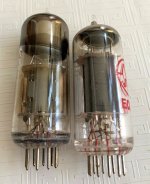
I don't like how they sound... look at the picture how different they are...
Obviously 6sn7 with CSS is border line to drive kt120.... alternatives are 6N6P, ECC99 and 12BH7 with lower Rp.
The ECC99 is new, widely available and sounds bolder and 'unforgiving' than 6sn7. I can buy it in matched sections which improves the performance, their only problems is they need frequent replacements to keep the amplifier performing.
Sonically the 6N6P is a big compromise vs. 6sn7, it is not as linear and subjectively not good.
The 12BH7 has less gain, higher Rp than ECC99, less heater current, so the ECC99 cost more but performs better, which is our goal, is to have an overkill driver a good step above what a 6sn7gt can do...
I could also use a 6BL7 going further in the trajectory of the ECC99, it is less linear, and at this point the current requirements are taxing up the B+ available for the output stage.
JJ designed that tube for driving the 300B and the 2A3, as a replacement for other tubes such as 5687, E182CC, 6840, and 6BL7.
I could not detect any sound degradation replacing a 6sn7gt NOS in LTP with the ECC99, to me it was not the most economical, but the best way forward to drive the KT120.
ECC99 are regularly used in the most expensive pre-amps, and dacs, a testimony to their performance with keeping small signals musical without adding or subtracting.
Attachments
Right, 6BX7 is a little more linear than the 6BL7 and has a little lower Rp, the tradeoff is a lower gain........
I did a comparison of the 6BX7 vs 6BL7, 6BL7 was the driver of choice for the 300B, maybe 6BX7 if you used two 300B???
The main idea here is to have the ECC99 LTP on top of a EL822, I'll try to make a schematic in LTSpice and post in the the following week!
I did a comparison of the 6BX7 vs 6BL7, 6BL7 was the driver of choice for the 300B, maybe 6BX7 if you used two 300B???
The main idea here is to have the ECC99 LTP on top of a EL822, I'll try to make a schematic in LTSpice and post in the the following week!
I've used 6SN7, 6N6P, 12BH7, 6CG7 and 6BL7's configured as LTP with a CCS supplied from a - 80v rail to drive multiple parallel OP stages cleanly up to OP's of 130w. Typical THD less than 1% at full power OP. I can't hear any difference to be honest.
There are other options, using two 12BH7/ECC99's parallel connected as a LTP or have a bash at using EL84 LTP like Patrick Turner did, see attached.
There are other options, using two 12BH7/ECC99's parallel connected as a LTP or have a bash at using EL84 LTP like Patrick Turner did, see attached.
Attachments

That’s not being weird. That’s being cheap (and/or lazy). The only problem with that is if you need 200V p-p you start having issues. You can always amplify after the concertina a and get all the output you want, but then you have a Williamson (or Williamson-ish) with the extra low frequency pole.
As mentioned a concertina has no gain, with a LTP all you need is a common cathode gain stage & LTP to drive the OP stage, so three valves in all, still, we all have our favourite designs that work for us.I'm weird - I never use LTP. Always split load AKA Concertina.
BTW Koda, why the split cathode resistors on the 12SN7's? also noticed some pretty big coupling caps value's, 1u! Why? Lastly with *SN7's 47k is the perfect anode resistor, it's my de-fault and I've seen it used in loads of design's. It's like the 100k Ra with ECC83's.
Last edited:
The extra resistors reduce gain slightly and allow for the large drive signal without going to cut off... 1µF (C1, C3) to make that pole so low it doesn't cause instability (220nF causes "breathing" or "motorboating" depending on the OPTs and output stage), C7, C8 are usually loaded with 100k and are a "normal" 1.6Hz pole.
The input shown is my "old version"... I now use a 2nd order input filter as shown in this complete version:
In practice, C8 and C9 are 1µF, not 330nF because it works better IMHO.

The input shown is my "old version"... I now use a 2nd order input filter as shown in this complete version:
In practice, C8 and C9 are 1µF, not 330nF because it works better IMHO.
Last edited:
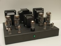
This was an old project developped around EL34 and KT120 ( in photo)
Alla is around a OT with the secondary single set at 3 ohm and primary at 3200 ( ratio is around 33)
In input a srpp of 6922 then a long tail with ECC99 or 6N6 (dc connection) ; the results is fine as linearity.
The configuration is pentode even I tested it also in triode mode.
Two power supply, one ss for output stage, the other with GZ34 for input/splitter.
The GFB is around 20 dB
The short info about power ( 2 % of THD)
KT120
900 mV in for 19,42 Volt on 8 ohm = 47 w
600 mV in for 17 Volt on 4 ohm = 72 w
Interesting is the increment of power when the 4 ohm is connected; this was the intial intention
Walter
Attachments
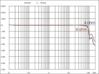
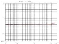
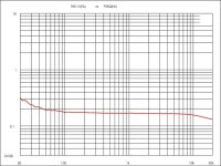
In attach the frequency response at 1 watt with 8 and 4 ohm load.
Some little indecision on high frequency but at 150 kHz; on FB there isn't compensation
Then the THD vs frequency at 10 watt; fine because is costant with frequency with a little increment at 20 kHz.
Then the triode configuration always at 10 watts, THD vs freq., also good
Some little indecision on high frequency but at 150 kHz; on FB there isn't compensation
Then the THD vs frequency at 10 watt; fine because is costant with frequency with a little increment at 20 kHz.
Then the triode configuration always at 10 watts, THD vs freq., also good
Attachments
It is strange that the THD is that high in pentode, 0.4 % ... In triode it is a little better 0.2% or close....
the power on test is 10 w rms, 9 volt / 8ohm
with 33 of ratio in the primary there are 297 Vrms a-a.
Walter
Hi,The input shown is my "old version"... I now use a 2nd order input filter as shown in this complete version:
In practice, C8 and C9 are 1µF, not 330nF because it works better IMHO.
I don't see any reason for separate cathode resistor arrangements for the 2nd tube, especially with respect to the fact that both cathode are risen by R23 or R28. A common resistor chain for both surely would improve symmetry, hence reduce 2nd order distortions.
Best regards!
- Home
- Amplifiers
- Tubes / Valves
- PP KT120 ... The last power amplifier