As a I am wrapping my current project (RH807 SE amp) I am thinking of the next project to build on this experience.
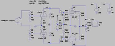
My DAC has 6.4V rms balanced outputs. So I was thinking of using this to design a PP amp without a phase splitter. Volume control would be done using a stereo stepped attenuator for channel. Would the topology a good starting point? Ignore the component values as I have not optimized the o.p. yet.
My DAC has 6.4V rms balanced outputs. So I was thinking of using this to design a PP amp without a phase splitter. Volume control would be done using a stereo stepped attenuator for channel. Would the topology a good starting point? Ignore the component values as I have not optimized the o.p. yet.
Attachments
Ow. Id look at the audio research front end on de D150
Right now you have two RC driver stages driven by a balanced source. If your DAC is AC balanced and DC ofsset the DC offset is gonna change the working point of one or the other tubes causing imbalance in the gain.
Another way is to take a INA105 and AC couple it into a tube amp like you normally would.
The DAC makes an excellent splitter, and better still, the differential to SE function - which is usually done with opamps on the DAC board - is performed by the output transformer.
High quality DACs (ESS) need the diff→SE to be performed properly (it cancels some common-mode distortions), and eliminating the opamps in that position is beneficial, IME.
Some reconstruction filtering is needed, but with some DACs this can be passive.
High quality DACs (ESS) need the diff→SE to be performed properly (it cancels some common-mode distortions), and eliminating the opamps in that position is beneficial, IME.
Some reconstruction filtering is needed, but with some DACs this can be passive.
Ow. Id look at the audio research front end on de D150
Right now you have two RC driver stages driven by a balanced source. If your DAC is AC balanced and DC ofsset the DC offset is gonna change the working point of one or the other tubes causing imbalance in the gain.
So why not just AC couple the differential input in case there is an DC offset? If i don't measure any DC offset then can I drive as drawn?
Edit: Clarification, my DAC has SE outputs as well. I wanted to take advantage of the balanced outputs to design a simple PP amp for it and take advantage of the healthy 6v RMS.
Last edited:
I just modelled a 5% gain imbalance in the driver stages. It adds some 2nd harmonic but its negligible. Might even sound better......
As a I am wrapping my current project (RH807 SE amp) I am thinking of the next project to build on this experience.
My DAC has 6.4V rms balanced outputs. So I was thinking of using this to design a PP amp without a phase splitter. Volume control would be done using a stereo stepped attenuator for channel. Would the topology a good starting point? Ignore the component values as I have not optimized the o.p. yet.
Why don't you finish the project you are on now. Still don't see any measured results.🙄
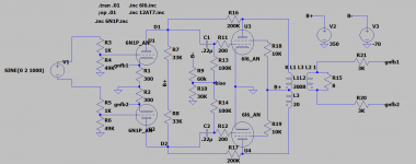
I would still have U1/U2 balanced LTP even if you drive it differentially. Just gives you more common mode rejection. You can also have differential feedback from the OPT.

I would still have U1/U2 balanced LTP even if you drive it differentially. Just gives you more common mode rejection. You can also have differential feedback from the OPT.
GNFB like this?
Attachments
So I was thinking of using this to design a PP amp without a phase splitter. Volume control
would be done using a stereo stepped attenuator for channel.
Also use a balanced volume control ( U-pad).
My dac is ballanced and therefore no phase splitter is needed indeed. Only a volume control and a buffer/gain stage. The preamp can drive the power tubes directly.
You may wish more gain with the GNFB and volume control as you already have plate to plate FB. The GNFB will give you some common mode rejection. You could also add say 100R + 470uF between the cathodes of U1 and U2 to up the gain. Only ideas.
Last edited:
This post's schematics, the tubes so far are of Balanced Amps; the tubes are not of Differential Amps.
The output stage is push pull, not differential.
No current sinks in the input tubes, no current sinks in the output tubes.
Just how I see it.
It is hard to balance those 4 tube's gains, from side to side.
If they are well balanced, a very very good precision stepped stereo volume control works.
Just as you said you would do.
Another solution is 2 precision resistors, one from (+ in), and one from (- in), and a rheostat across their outputs.
That is intrinsically very well balanced, over the full range of the rheostat.
Last edited:
How close to those gains need to be matched? I did a little sim in spice and a 5% mismatch in one stage only added a negligible amount of 2nd H.
You got me there. I need time to think about it.
But 5% error is -26dBc. Thats what occurs to me off the top of my head.
That sounds like 5% Harmonic Distortion to me.
Perhaps the other half of the circuit cut the 5% in half to 2.5%, -32dBc.
What 2nd Harmonic Distortion did the simulation give you?
But 5% error is -26dBc. Thats what occurs to me off the top of my head.
That sounds like 5% Harmonic Distortion to me.
Perhaps the other half of the circuit cut the 5% in half to 2.5%, -32dBc.
What 2nd Harmonic Distortion did the simulation give you?
Last edited:
A single current sink feeding both output cathodes in parallel, will restrict the circuit to Class A, any thing beyond that will be clipping. I have done that, and in my case the clipping was quite soft, until it was way overdriven.
With the separate cathodes and resistor self bias, or with separate cathodes and fixed bias, it can come out of Class A, and go into Class AB, and get additional power before it finally reaches clipping.
Tradeoffs.
Do not forget to match the output tube plate currents. Your output transformer will love you, and will not saturate early.
What is the advantage of using unbypassed screen resisters? You were going to get us some data on that in your previous thread. Why design something in when you don't know what it does?
You could run both screens thru an unbypassed 5K screen resistor & get some common mode rejection. That means lower even order D%, 2nd, 4th, 6th & so on.
You could run both screens thru an unbypassed 5K screen resistor & get some common mode rejection. That means lower even order D%, 2nd, 4th, 6th & so on.
- Home
- Amplifiers
- Tubes / Valves
- PP amp driven with balanced input source