3-Phase, 120 to Neutral, 208 Single Phase across any two phases.there is a way to convert 3 phase into 2 phase. I don't think you can get it down to single phase though, unless you throw out half the power
Common in apartment & commercial buildings, For audio European
PTs would probably be OK.
The whole point, IMO of this amp is that it has no gNFB. In my ideal world, I'd swap in a 5687 or 6H6Pi LTP for the input stage over that 12AU7.
Douglas
Douglas
Personally, I wouldn't call it the whole point. Local feedback seems better regarded than GNFB in general and it's probably a good thing if an amp can get away with only local feedback (or no feedback at all, but that is perhaps a special interest for purists). In my special case, driving big subwoofers, I imagine it could be a good thing to use a healthy dose of local NFB and then add some GNFB to counteract the Dcr in the OPTs a bit and push the damping factor up a but further.The whole point, IMO of this amp is that it has no gNFB
There were posts in Tubes / Valves about single ended amplifiers that used negative resistance output stages, to control the woofer.
Might have been me. Refer to the following
Early PP 6AQ5 Amp with Voltage & Current FB
________________________________________
The back page on this one tells me I built it Aug 1956. It went to a former Luftwaffe pilot I met while working at DeHavilland, an aircraft factory in Canada. He eventually became a dentist & practiced here for many years.
Other than the positive current FB sensed by a short piece of resistance wire this amplifier is very ordinary. Positive current FB reduces the output impedance. The connexion to the current sense could be just as well hooked up the other way round in which case the current FB becomes negative & output impedance would increase. Or a low value resister on each side of the common with a pot across the pair & the FB can be adjusted from positive to negative. That is how Electrovoice & others did it.
Negative output impedance can be easily had which cancels some of the speaker voice coil resistance. The speaker resonant peak inverts, too much FB & the circuit becomes unstable.
All the iron is Hammond. The OPT is meant for a public address amplifier, only limited NFB is possible. The Hammond 1600 series today is much better.
There was some HF ringing at the front edge of square waves, that was mostly fixed by a ‘gimmick’, a short piece of insulated wire tied to one of the OPT primary leads. In some unrelated tests later I found there is something like 200 pF more capacity to the OPT core from one of the primary leads than the other. I’ve included some tests I used to sort out that problem here. The capacity unbalance does create more problems when stabilizing a FB amplifier. I’m sure the Hammond OPTs of today are much better than in the 50s.
There are several articles covering amplifiers like this in Volume 3 of Audio Anthologies published by Audio Amateur Press, 1990
Attachments
-
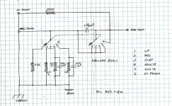 6AQ5 PP Amplifier with Positive Curent Feedback Input Selector.jpg424.7 KB · Views: 140
 -
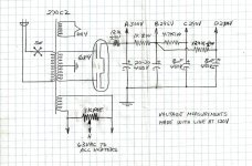 6AQ5 PP Amplifier with Positive Curent Feedback Power Supply.jpg377.9 KB · Views: 131
 -
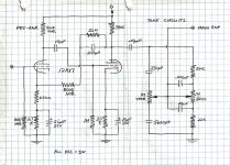 6AQ5 PP Amplifier with Positive Curent Feedback Preamp & Tone Controls.jpg534.9 KB · Views: 143
 -
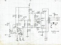 6AQ5 PP Amplifier with Positive Curent feedback Output Stage.jpg603.9 KB · Views: 151
Last edited:

jhstewart9,
Thanks!
I was not aware of your 6AQ5 pp with current feedback article.
Negative Resistance
1. At the time that I remembered someone posting about a negative resistance amplifier I was having another temporary brain memory loss.
With part of my memory back, I remember that Wavebourn posted about his negative resistance amplifiers.
A different form of push pull
2. I had posted about using 2 single ended amplifiers; driving their inputs in opposite phase; and connecting their secondaries in opposite phase.
With 2 single ended air gapped transformers, the idea was to never have zero current in the primaries, and to keep a minimum level of magnetism in each of the two sets of laminations.
I did not make it clear what I had already done, so smoking amp quoted part of my post.
My post was quoted by smoking-amp in the box:
"I suspect that will give you pretty close to a P-P OT, except for 6X the $$$, but this is DIY after all. Would be interesting to see what happens to the sum of the OT magnetizing currents. Maybe a simulation would tell."
3. Because the theory for using 2 SE air gapped transformers to do push pull seemed to be dismissed (even though the French did it before I did),
I defended my theory with an un-scientific testimony:
Just as jhstewart9 partially quoted . . . I said: "All I know about the special case push pull that uses 2 SE air gapped transformers,"
and unquoted part of my sentence: "it sounded good, and not just to me".
(It was heard by many other listeners too).
Yes, I do know something about that design idea, I built it, I measured it, and we had multiple listeners hear it.
Thanks!
I was not aware of your 6AQ5 pp with current feedback article.
Negative Resistance
1. At the time that I remembered someone posting about a negative resistance amplifier I was having another temporary brain memory loss.
With part of my memory back, I remember that Wavebourn posted about his negative resistance amplifiers.
A different form of push pull
2. I had posted about using 2 single ended amplifiers; driving their inputs in opposite phase; and connecting their secondaries in opposite phase.
With 2 single ended air gapped transformers, the idea was to never have zero current in the primaries, and to keep a minimum level of magnetism in each of the two sets of laminations.
I did not make it clear what I had already done, so smoking amp quoted part of my post.
My post was quoted by smoking-amp in the box:
smoking-amp's response to that:Connect one output plate to the primary of an SE air gapped transformer, and the other end of the primary to B+
And Connect the other output plate to the primary of a second SE air gapped transformer, and the other end of the primary to B+
Now,
"I suspect that will give you pretty close to a P-P OT, except for 6X the $$$, but this is DIY after all. Would be interesting to see what happens to the sum of the OT magnetizing currents. Maybe a simulation would tell."
3. Because the theory for using 2 SE air gapped transformers to do push pull seemed to be dismissed (even though the French did it before I did),
I defended my theory with an un-scientific testimony:
Just as jhstewart9 partially quoted . . . I said: "All I know about the special case push pull that uses 2 SE air gapped transformers,"
and unquoted part of my sentence: "it sounded good, and not just to me".
(It was heard by many other listeners too).
Yes, I do know something about that design idea, I built it, I measured it, and we had multiple listeners hear it.
Last edited:
Bandersnatch,
Yes.
I simply took one SE stereo amplifier, then fed the L and R channels from the two phases of a phase inverter.
Either I reversed the plate and B+ of the Left primary,
Or I reversed the common and 8 of one secondary . . effectively connecting Left 8 to Right common, and Left common to Right 8.
Either way works, but not both changes of connections at the same time, it will short out the signals.
Last edited:
Re: Current-starved operation of driver pentodes with local feedback from output tubes plates to driver tubes cathodes...
Looking through old emails, I found this circuit from a diyAudio post from about a year ago. It's a schematic from a Western Electric amplifier using a differential pair of 348A (similar to 6J7) driving a pair of 349A (similar to 6F6 or 6V6), again using that local negative feedback scheme from output pentode plate to driver pentode cathode.

The output pentode plate (349A) to driver pentode (348A) cathode feedback resistor is 300k ohms.
Note the voltages on the 348A differential driver pair.
The voltage at each cathode is 1.65V.
That voltage drop across 1600 ohms means plate+screen plus feedback current for each 348A is 1.03mA.
The 349A plate voltage is 270V, while the 348A cathode voltage is 1.65V. That's 270 - 1.65 = 268.35V.
268.35V dropped across 300k ohms means current draw there is approximately 0.895mA.
Plate voltage isn't shown, but the voltage at the screen grids is way down at only 32V.
The B+ voltage to the 348A pair is only 208V. The screen resistor is 1M ohms. 208V - 32V = 176V, which divided by 1M = plate current of 176uA for both 348As, or 0.088mA plate current for each 348A.
So now we have 0.895mA + 0.088mA = 0.983mA
Each 348A draws 1.03mA, so 1.03 - 0.983 = a very measly 0.047mA plate current for each 348A.
Each 348A has a plate load resistor of 500k ohms.
500,000(0.000047) = 23V dropped across the plate resistor, so plate voltage = 203V - 23V = 180V.
That all works out to:
Vp = 180V
Ip = 47uA
Vg2 = 32V
Ig2 = 88uA
Infb = 942uA
Vk = 1.65V
Ik = 1.03mA
Here we have an extreme version of that diff-pair pentode driver in a current-starved state.
So the RCA engineers were not the only ones using this concept at the time. The question remains why this topology was so completely abandoned by 1965. Which makes me curious to build the proposed updated RCA circuit. Life's been in the way lately, but I need to get started on this thing...
Looking through old emails, I found this circuit from a diyAudio post from about a year ago. It's a schematic from a Western Electric amplifier using a differential pair of 348A (similar to 6J7) driving a pair of 349A (similar to 6F6 or 6V6), again using that local negative feedback scheme from output pentode plate to driver pentode cathode.
The output pentode plate (349A) to driver pentode (348A) cathode feedback resistor is 300k ohms.
Note the voltages on the 348A differential driver pair.
The voltage at each cathode is 1.65V.
That voltage drop across 1600 ohms means plate+screen plus feedback current for each 348A is 1.03mA.
The 349A plate voltage is 270V, while the 348A cathode voltage is 1.65V. That's 270 - 1.65 = 268.35V.
268.35V dropped across 300k ohms means current draw there is approximately 0.895mA.
Plate voltage isn't shown, but the voltage at the screen grids is way down at only 32V.
The B+ voltage to the 348A pair is only 208V. The screen resistor is 1M ohms. 208V - 32V = 176V, which divided by 1M = plate current of 176uA for both 348As, or 0.088mA plate current for each 348A.
So now we have 0.895mA + 0.088mA = 0.983mA
Each 348A draws 1.03mA, so 1.03 - 0.983 = a very measly 0.047mA plate current for each 348A.
Each 348A has a plate load resistor of 500k ohms.
500,000(0.000047) = 23V dropped across the plate resistor, so plate voltage = 203V - 23V = 180V.
That all works out to:
Vp = 180V
Ip = 47uA
Vg2 = 32V
Ig2 = 88uA
Infb = 942uA
Vk = 1.65V
Ik = 1.03mA
Here we have an extreme version of that diff-pair pentode driver in a current-starved state.
So the RCA engineers were not the only ones using this concept at the time. The question remains why this topology was so completely abandoned by 1965. Which makes me curious to build the proposed updated RCA circuit. Life's been in the way lately, but I need to get started on this thing...
Last edited:
I missed that. You're right.
The driver plate voltage is only 15V?? Could that be a typo?
Man, that would be extremely voltage starved!
I haven't drawn a load line for that, but it can't be pretty. WE did some wacky stuff sometimes....
Edit to add:
If the 348A Vp is only 15V, and the B+ there is 203V, that means 203V - 15V = 188V dropped across 500k ohms = 376uA
That would be more similar to the operating points RCA chose for the 6AU6 drivers, but still... only 15V at the 348A plates? That's too weird.
Last edited:
I have had some extra thoughts, and I may use a 6AH6 biased at 5mA rather than a 6AU6 for a little more transconductance. I have an inquiry in to Apex Jr. for 100 pieces of his PC mount 7-pin socket.
You're going to be beat me to this. I had a major surgery 10/31 and am recovering. That's going well so far. I'll be back, but for now, no hobbies, concentrating on healing up.
Even though I can't do any soldering or lift things yet, I can certainly try to plan this out so once I start I can actually complete this project. So...
What do you all know about the 6BN11 dual pentode tube? (https://tubedata.jp/sheets/123/6/6BN11.pdf)
It's a twin pentode in a 12-pin compactron envelope. PP driver stage in one bottle?
6BN11:
Max Va = 330V
Max Vg2 = 330V (depending on op conditions)
Max Pdiss = 3.1 W
gm = 13 mA/V
What do you all know about the 6BN11 dual pentode tube? (https://tubedata.jp/sheets/123/6/6BN11.pdf)
It's a twin pentode in a 12-pin compactron envelope. PP driver stage in one bottle?
6BN11:
Max Va = 330V
Max Vg2 = 330V (depending on op conditions)
Max Pdiss = 3.1 W
gm = 13 mA/V
I think each pentode in a 6BN11 is nearly equivalent to a 6EW6.
6EW6:
Va = 125V
Vg2 = 125V
Vg1 = -0.8V
Ia = 11mA
Ig2 = 3.2mA
gm = 14mA/V
6BN11:
Va = 125V
Vg2 = 125V
Vg1 = -0.83V
Ia = 11mA
Ig2 = 3.8mA
gm = 13mA/V
Does anyone know of a closer equivalent to 6BN11?
6EW6:
Va = 125V
Vg2 = 125V
Vg1 = -0.8V
Ia = 11mA
Ig2 = 3.2mA
gm = 14mA/V
6BN11:
Va = 125V
Vg2 = 125V
Vg1 = -0.83V
Ia = 11mA
Ig2 = 3.8mA
gm = 13mA/V
Does anyone know of a closer equivalent to 6BN11?
I would definitely consider tuning each side of the 6BN11 for plate current individually in the interest of matching transconductance between sides. Side-side matching is likely to be haphazard.
That's a good point about the need to match gm of each pentode section. It would be much easier to use 7pin (single) pentodes and sort them for matched pairs. The chances of getting a decent match of two pentode sections in a single bottle are pretty low. I guess I'll abandon the 6BN11 idea and just go with the more widely available and affordable 6AU6/6EW6/6CB6 family. KISS.
- Home
- Amplifiers
- Tubes / Valves
- PP 6V6 amp from RCA RC-19 manual -- Thoughts?